


Mikroelektronika d.o.o.
Tableau à clic Motion 2
Tableau à clic Motion 2
SKU: MIKROE-4059
Impossible de charger la disponibilité du service de retrait


Overview
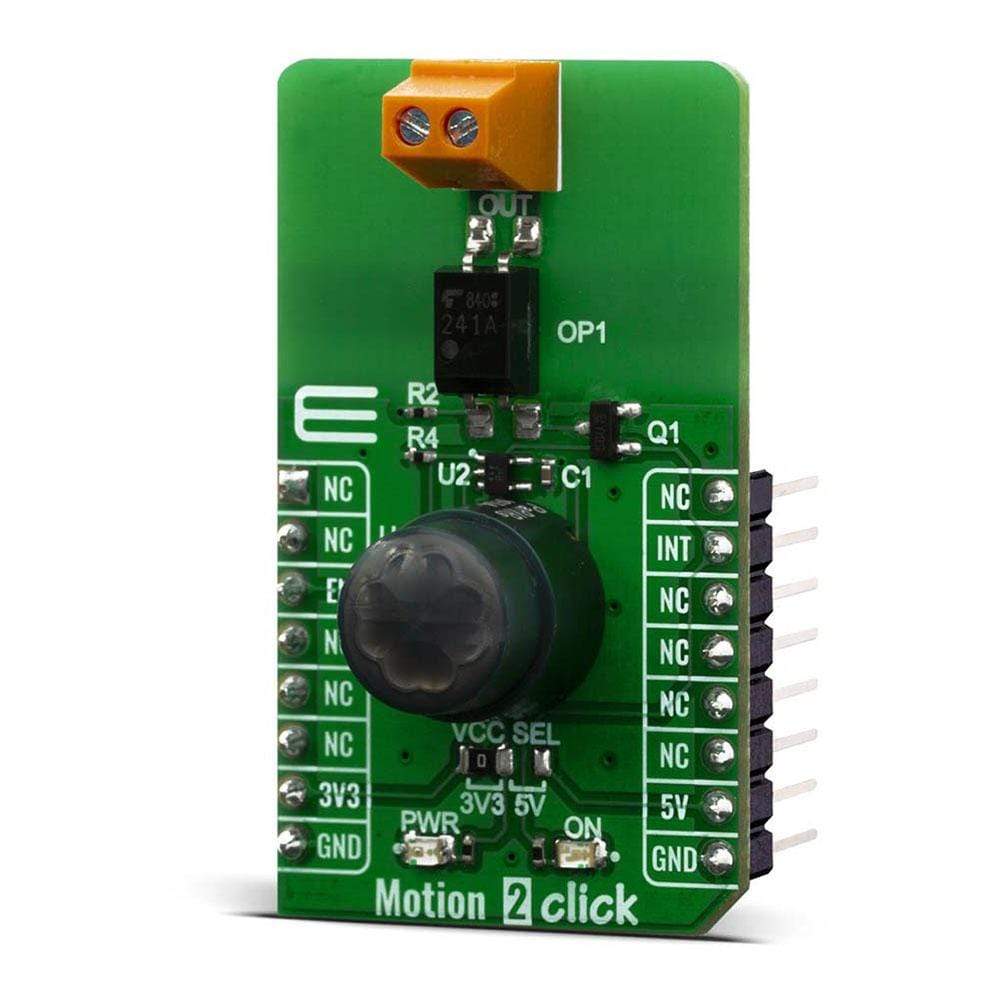
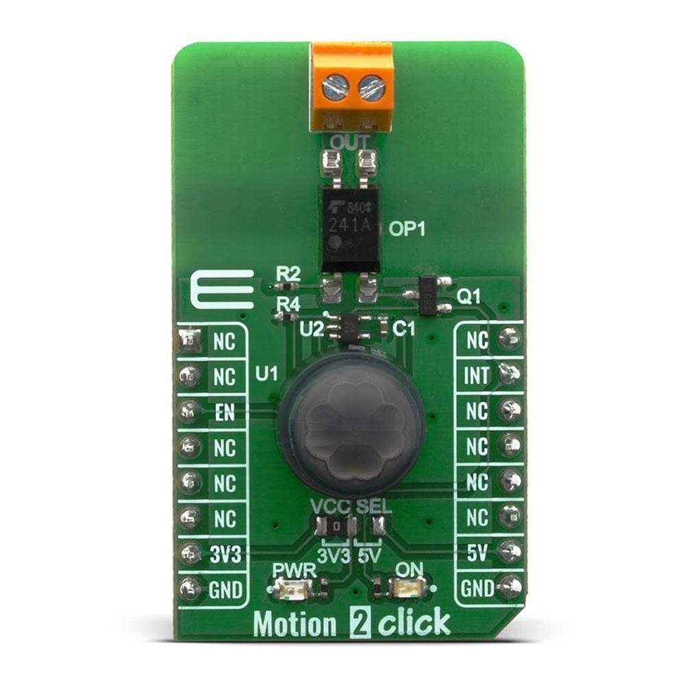
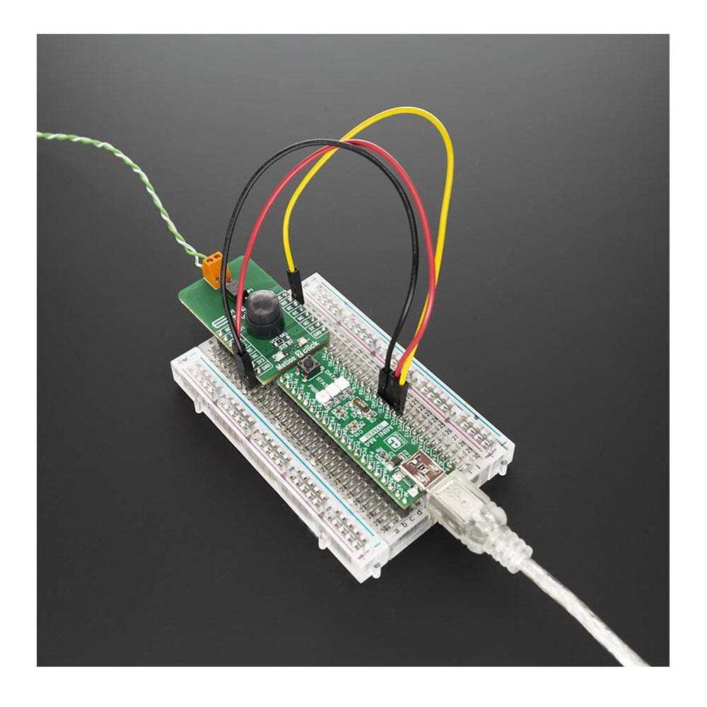
the The Motion 2 Click Board™ is based on the EKMC1607112, PIR motion sensor from Panasonic Corporation that's used as a human motion detector. Also featured on Motion 2 Click Board™ is TLP241A photo relay from Toshiba that is used to provide reinforced galvanic isolation for the external signals used to drive some external high power electronic equipment when motion is detected. It's allowing up to 40V between the SSR contacts in the OFF state, and currents up to 2A while in the ON state, thanks to a very low ON-state resistance.
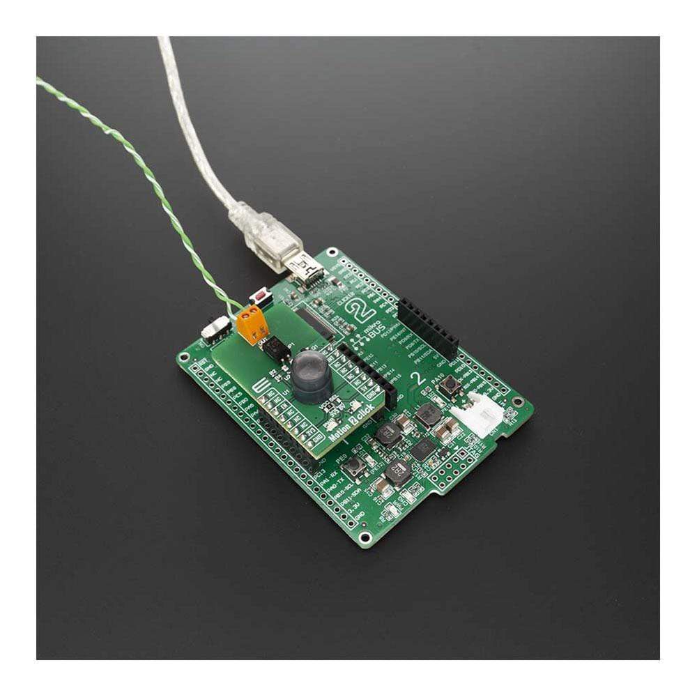
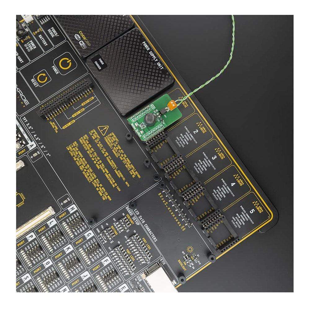
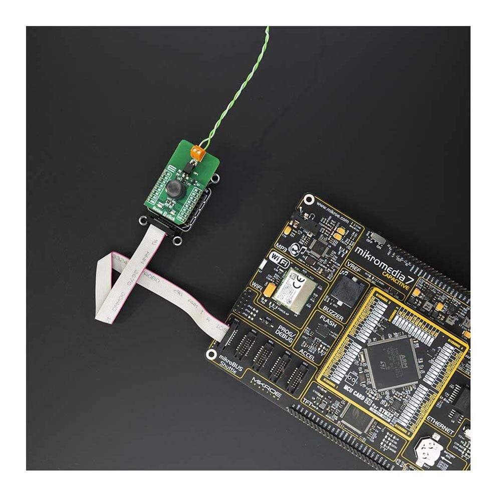
The Motion 2 Click Board™ is supported by a mikroSDK compliant library, which includes functions that simplify software development. This Click Board™ comes as a fully tested product, ready to be used on a system equipped with the mikroBUS™ socket.
Downloads
Le Motion 2 Click Board™ est Basé sur le capteur de mouvement PIR EKMC1607112 de Panasonic Corporation, utilisé comme détecteur de mouvement humain. Le Motion 2 Click Board™ comprend également un relais photoélectrique TLP241A de Toshiba qui est utilisé pour fournir une isolation galvanique renforcée pour les signaux externes utilisés pour piloter certains équipements électroniques externes de haute puissance lorsqu'un mouvement est détecté. Il permet jusqu'à 40 V entre les contacts SSR à l'état OFF et des courants jusqu'à 2 A à l'état ON, grâce à une très faible résistance à l'état ON.
La carte Motion 2 Click Board™ est supportée par une bibliothèque compatible mikroSDK, qui comprend des fonctions qui simplifient le développement logiciel. Cette carte Click Board™ est un produit entièrement testé, prêt à être utilisé sur un système équipé du socket mikroBUS™.
| General Information | |
|---|---|
Part Number (SKU) |
MIKROE-4059
|
Manufacturer |
|
| Physical and Mechanical | |
Weight |
0.02 kg
|
| Other | |
EAN |
8606018717163
|
Frequently Asked Questions
Have a Question?
Be the first to ask a question about this.