Tableau de clics couleur 10
Overview
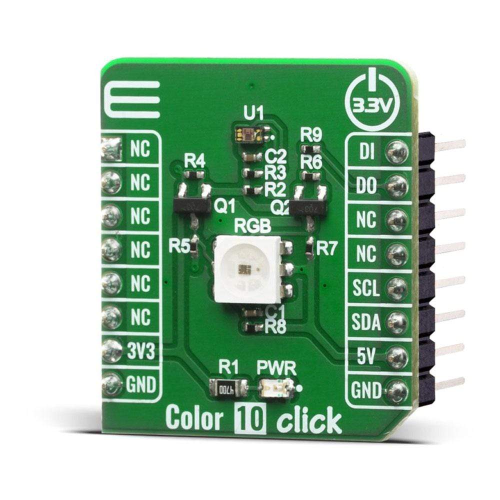
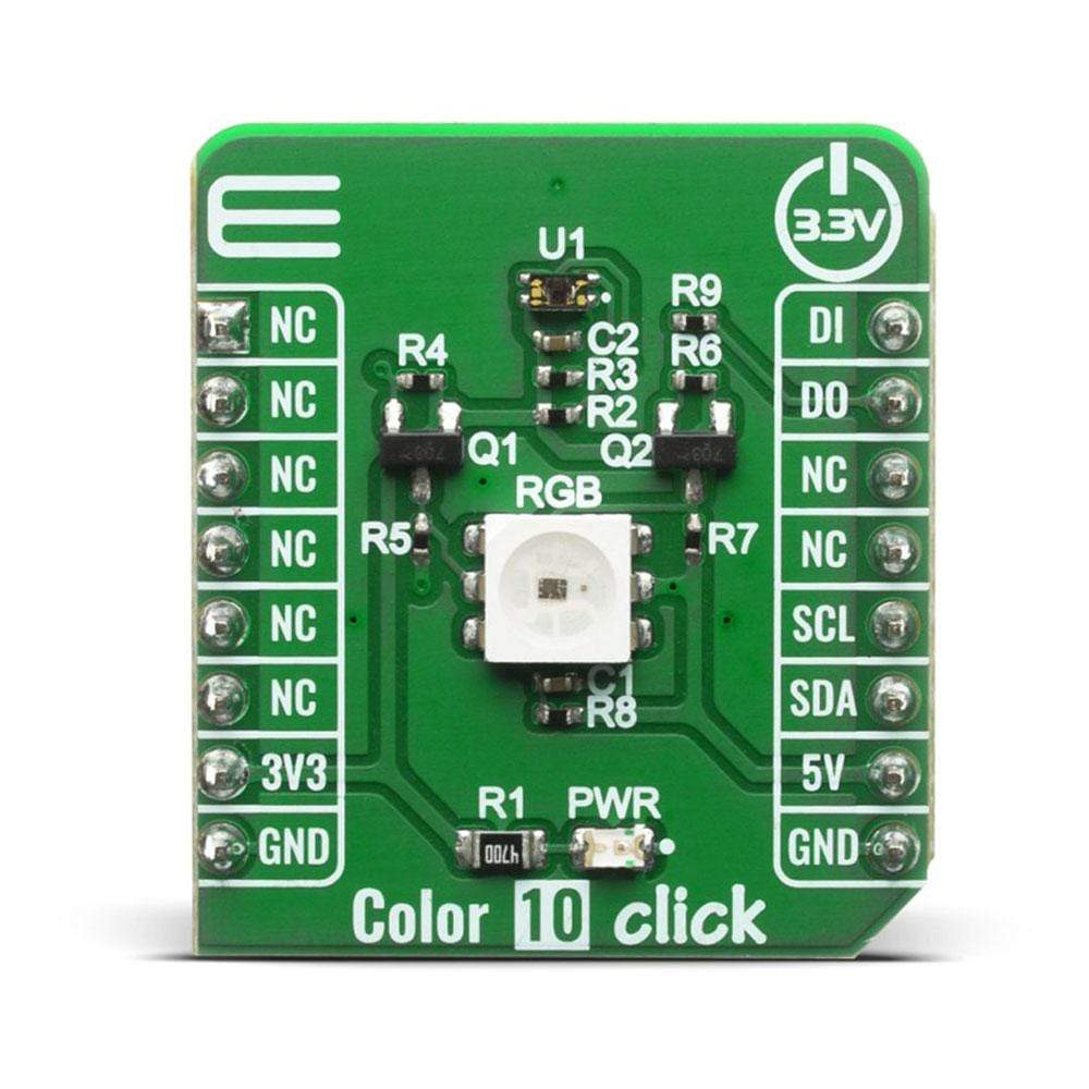
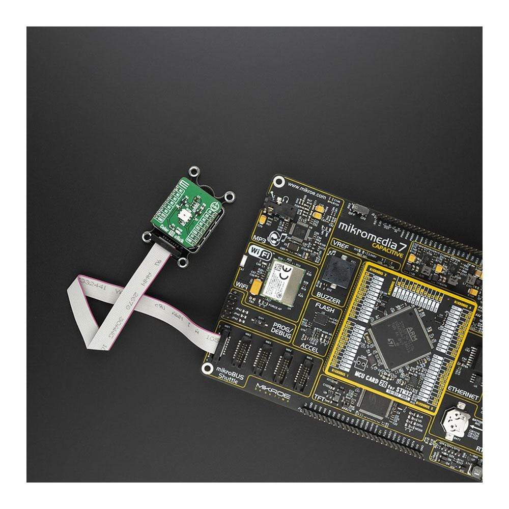
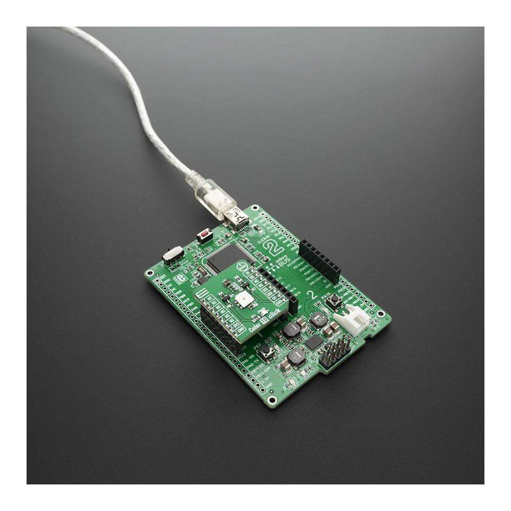
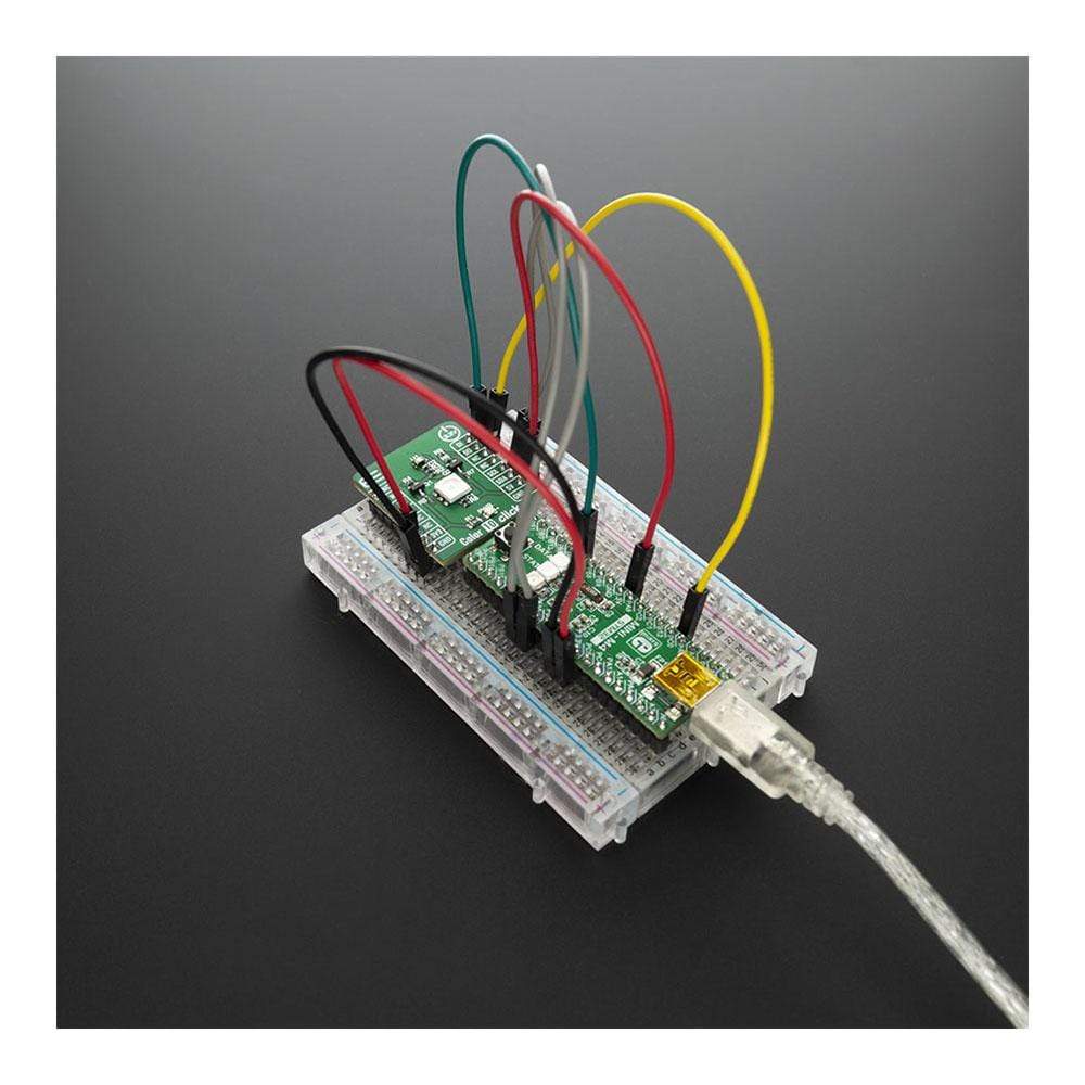
La carte Color 10 Click Board™ est équipée d'un capteur VEML3328 pour la détection de lumière RVB et IR ainsi que de la diode RVB intégrée à la carte, ce qui en fait un bon dispositif de détection des couleurs lorsqu'elle est combinée à une LED blanche. Le capteur VEML3328 détecte la lumière rouge, verte, bleue, claire et IR en incorporant des photodiodes, des amplificateurs et des circuits analogiques/numériques dans une seule puce CMOS.
Grâce à ce capteur, la luminosité et la température de couleur du rétroéclairage d'un écran peuvent être ajustées en fonction de la source de lumière ambiante et peuvent différencier les environnements d'éclairage intérieur et extérieur.
How Does The Color 10 Click Board™ Work?
The Color 10 Click Board™ is based on VEML3328, a RGB and IR light sensor from Vishay. This sensor is a 16-bit, low power, high sensitivity CMOS color sensor and signal conditioning IC, that can be operated via a simple I2C commands. This sensor has many features that make it a perfect solution for small designs such as the Color 10 Click Board™. One of these features is certainly its high level of integration that allows a minimal number of external components.
VEML3328 provides excellent temperature compensation capability for keeping the output stable under changing temperature. The sensor's functions are easily operated via the simple command format of I2C (SMBus compatible) interface protocol. VEML3328 has a low operating voltage range of 2.6V to 3.6V, integrated modules, color sensor and signal conditioning IC, supports low transmittance (dark) lens design and provides 16-bit resolution for each channel (R, G, B, C, and IR).
The WS2812 on the Color 10 Click Board™ can be used for testing purposes as well as the light source for object color detector, since VEML3328 can detect the color which WS2812 emits in R, G, B range. For clear and IR light, appropriate photodiodes should be used.
The WS2812 can be controlled by data protocol on DI and DO pins, data transfer protocol use single NZR communication mode. After the pixel power-on reset, the DI port receive data from microcontroller, the first pixel collect initial 24bit data then sent to the internal data latch, the other data which reshaping by the internal signal reshaping amplification circuit sent to the next cascade pixel through the DO port. After transmission for each pixel, the signal to reduce 24bit pixel adopt auto reshaping transmit technology, making the pixel cascade number is not limited the signal transmission, only depend on the speed of signal transmission.
SPECIFICATIONS
Type | Optical |
Applications | Can be used for adjusting brightness and color temperature of a display backlight based on the ambient light source, and it can differentiate indoor from outdoor lighting environment, and many other applications |
On-board modules | VEML3328, color sensor and signal conditioning IC |
Key Features | 16-bit resolution for each channel (R, G, B, C, and IR), low power consumption I 2 C (SMBus compatible) interface on board RGB light source for calibration and object color sensing. |
Interface | GPIO,I2C |
Compatibility | mikroBUS |
Click board size | S (28.6 x 25.4 mm) |
Input Voltage | 3.3V,5V |
PINOUT DIAGRAM
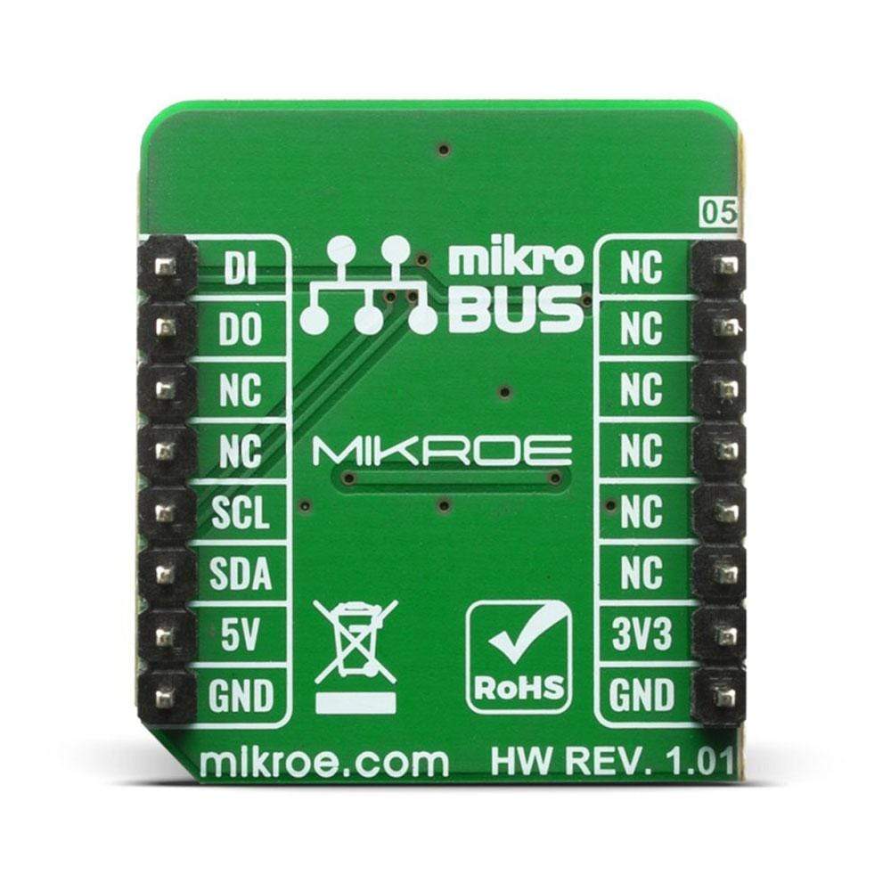
This table shows how the pinout of the Color 10 Click Board™ corresponds to the pinout on the mikroBUS™ socket (the latter shown in the two middle columns).
Notes | Pin | Pin | Notes | ||||
---|---|---|---|---|---|---|---|
NC | 1 | AN | PWM | 16 | DI | Data Signal Input | |
NC | 2 | RST | INT | 15 | DO | Data Signal output | |
NC | 3 | CS | RX | 14 | NC | ||
NC | 4 | SCK | TX | 13 | NC | ||
NC | 5 | MISO | SCL | 12 | SCL | I2C Clock | |
NC | 6 | MOSI | SDA | 11 | SDA | I2C Data | |
Power Supply | 3.3V | 7 | 3.3V | 5V | 10 | 5V | Power supply |
Ground | GND | 8 | GND | GND | 9 | GND | Ground |
ONBOARD SETTINGS AND INDICATORS
Label | Name | Default | Description |
---|---|---|---|
LD1 | PWR | - | Power LED Indicator |
LD2 | WS2812 | - | Controllable RGB light power source |
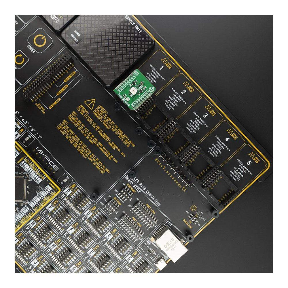
We provide a library for the Color 10 Click Board™ on our LibStock page, as well as a demo application (example), developed using MikroElektronika compilers. The demo can run on all the main MikroElektronika development boards.
Library Description
Library provides functions for reading color registers from device. Converting data to HSL color data, and automatically reading predefined colors;
Key Functions
uint16_t color10_generic_read ( uint8_t cmd_addr );
- Generic read function from devicefloat color10_get_color_value ( void );
- Functions for read HSL color valueuint8_t color10_get_color ( float color_value );
- Functions for detecting colors from HSL value
Example Description
The application is composed of three sections :
- System Initialization - Inicializes I2C module
- Application Initialization - Initialization driver init, checks device ID and sets default configuration
- Application Task - Reads color IR ADC value and then checks for predefined colors with write_color funcion
void application_task ( ) { uint16_t read_data; float color_data; read_data = color10_generic_read( COLOR10_CMD_REG_IR ); WordToStr( read_data, demo_txt ); mikrobus_logWrite( " - IR value: ", _LOG_TEXT ); mikrobus_logWrite( demo_txt, _LOG_LINE ); mikrobus_logWrite( " - Color: ", _LOG_TEXT ); write_color( ); mikrobus_logWrite( " *************** ", _LOG_LINE ); Delay_ms( 1000 ); }
Additional Functions :
- void write_color ( float color_val ) - Reads and gets color HSL value and then checks for the color and logs a few predefined colors
The full application code, and ready to use projects can be found on our LibStock page.
Other mikroE Libraries used in the example:
- I2C
- UART
Additional Notes and Information
Depending on the development board you are using, you may need USB UART click, USB UART 2 click or RS232 click to connect to your PC, for development systems with no UART to USB interface available on the board. The terminal available in all MikroElektronika compilers, or any other terminal application of your choice, can be used to read the message.
MIKROSDK
The Color 10 Click Board™ is supported with mikroSDK - MikroElektronika Software Development Kit. To ensure proper operation of mikroSDK compliant Click board™ demo applications, mikroSDK should be downloaded from the LibStock and installed for the compiler you are using.
Frequently Asked Questions
Have a Question?
Be the first to ask a question about this.