


Mikroelektronika d.o.o.
Carte IMU 6DOF 10 clics
Carte IMU 6DOF 10 clics
SKU: MIKROE-3934
Impossible de charger la disponibilité du service de retrait


Overview
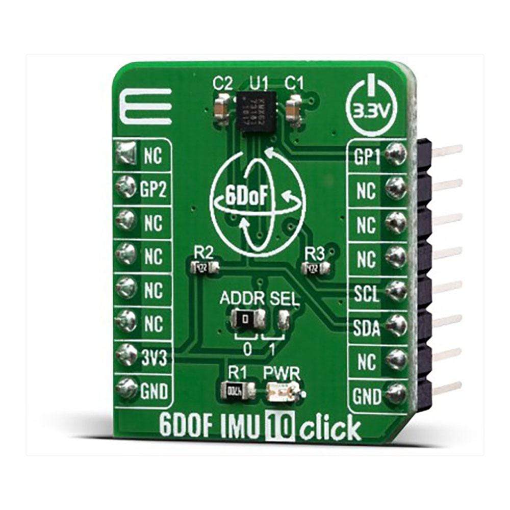
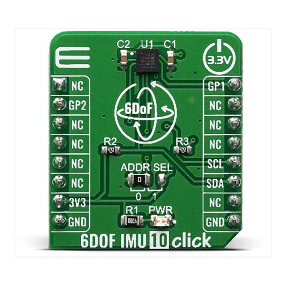
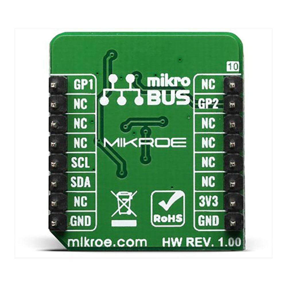
The 6DOF IMU 10 Click Board™ is a 6 Degrees-of-Freedom inertial sensor module, that features a KMX62 sensor which consists of a tri-axial magnetometer (range ±2g / ±4g / ±8g / ±16g) plus a triaxial accelerometer (±1200µT). The accelerometer and magnetometer data can be accumulated in an internal 384-byte FIFO buffer and transmitted to the Application Processor. This Click Board™ can be used for applications that require movement and orientation features, navigation, such as screen orientation, machine/vibration analysis, game playing.
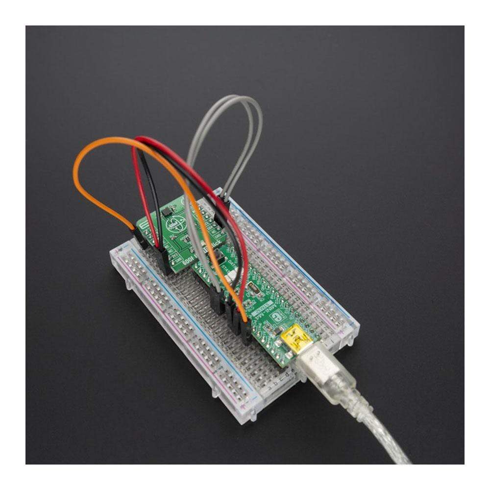
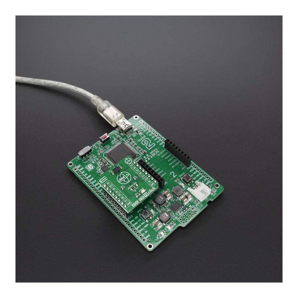
The 6DOF IMU 10 Click is supported by a mikroSDK compliant library, which includes functions that simplify software development. This Click Board™ comes as a fully tested product, ready to be used on a system equipped with the mikroBUS™ socket.
Downloads
Le module Click Board™ 6DOF IMU 10 est un module de capteur inertiel à 6 degrés de liberté, doté d'un capteur KMX62 composé d'un magnétomètre triaxial (plage ±2g / ±4g / ±8g / ±16g) et d'un accéléromètre triaxial (±1200µT). Les données de l'accéléromètre et du magnétomètre peuvent être accumulées dans une mémoire tampon FIFO interne de 384 octets et transmises au processeur d'application. Ce Click Board™ peut être utilisé pour les applications qui nécessitent des fonctions de mouvement et d'orientation, de navigation, telles que l'orientation de l'écran, l'analyse des machines/vibrations, les jeux.
L' IMU 6DOF 10 Click est pris en charge par une bibliothèque compatible mikroSDK, qui comprend des fonctions qui simplifient le développement logiciel. Cette Click Board™ est un produit entièrement testé, prêt à être utilisé sur un système équipé du socket mikroBUS™.
| General Information | |
|---|---|
Part Number (SKU) |
MIKROE-3934
|
Manufacturer |
|
| Physical and Mechanical | |
Weight |
0.017 kg
|
| Other | |
EAN |
8606018718924
|
Frequently Asked Questions
Have a Question?
Be the first to ask a question about this.