

Mikroelektronika d.o.o.
Chargeur 11 Click Board
Chargeur 11 Click Board
SKU: MIKROE-3650
Impossible de charger la disponibilité du service de retrait


Overview
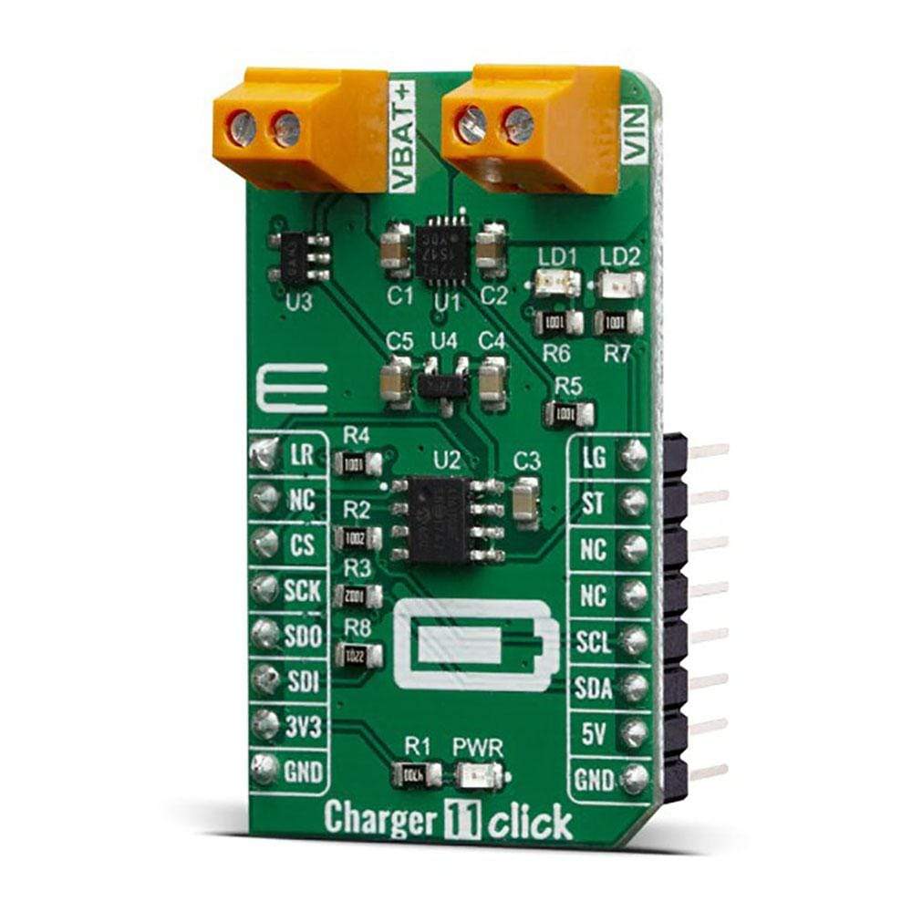
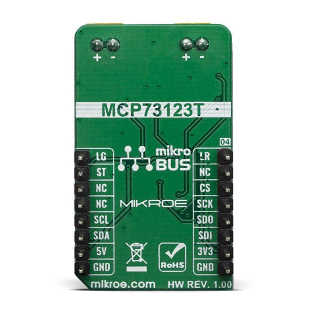
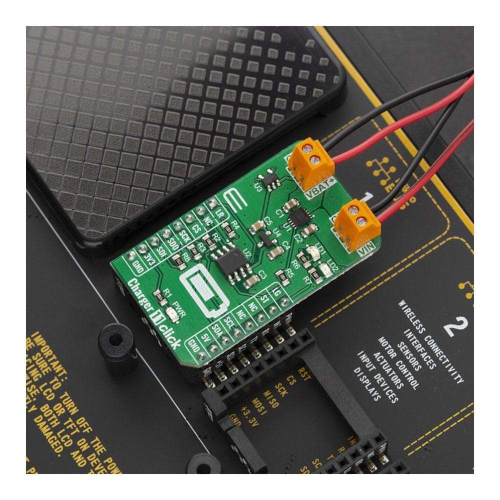
The Charger 11 Click Board™ is a LiFePO4 (lithium iron phosphate) battery charger. This Click Board™ can be used for Low-Cost LiFePO4 battery chargers, or Power Tools, toys, backup energy storage solutions, etc. The Charger 11 Click Board™ is based on the MCP73123T controller which has some extra features enabling charging without too much hassle.
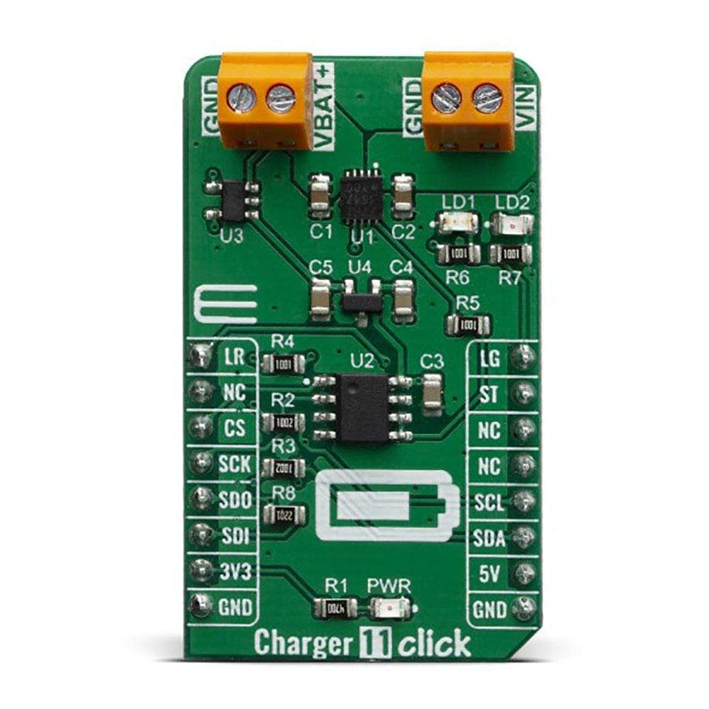
The Charger 11 Click Board™ features charge current control which uses an SPI interface through MCP4161 IC, which is an 8-bit digital potentiometer. For battery voltage monitoring this Click Board™ board uses MCP3221A5T analogue to digital converter through the I2C interface. On the board, there is a Power LED and two extra LED’s which can be used for charging indications.
Downloads
Le Charger 11 Click Board™ est un chargeur de batterie LiFePO4 (phosphate de fer lithium). Ce Click Board™ peut être utilisé pour les chargeurs de batterie LiFePO4 à faible coût, ou les outils électriques, les jouets, les solutions de stockage d'énergie de secours, etc. Le Charger 11 Click Board™ est basé sur le contrôleur MCP73123T qui possède quelques fonctionnalités supplémentaires permettant une charge sans trop de tracas.
Le chargeur 11 Click Board™ est doté d'un contrôle du courant de charge qui utilise une interface SPI via le circuit intégré MCP4161, qui est un potentiomètre numérique 8 bits. Pour la surveillance de la tension de la batterie, cette carte Click Board™ utilise un convertisseur analogique-numérique MCP3221A5T via l'interface I2C. Sur la carte, il y a une LED d'alimentation et deux LED supplémentaires qui peuvent être utilisées pour les indications de charge.
| General Information | |
|---|---|
Part Number (SKU) |
MIKROE-3650
|
Manufacturer |
|
| Physical and Mechanical | |
Weight |
0.021 kg
|
| Other | |
EAN |
8606018716371
|
Frequently Asked Questions
Have a Question?
Be the first to ask a question about this.