


Mikroelektronika d.o.o.
Panneau à 3 clics H-Bridge
Panneau à 3 clics H-Bridge
SKU: MIKROE-3613
Impossible de charger la disponibilité du service de retrait


Overview
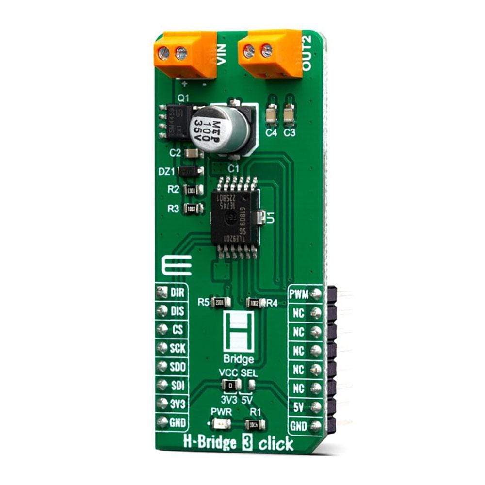
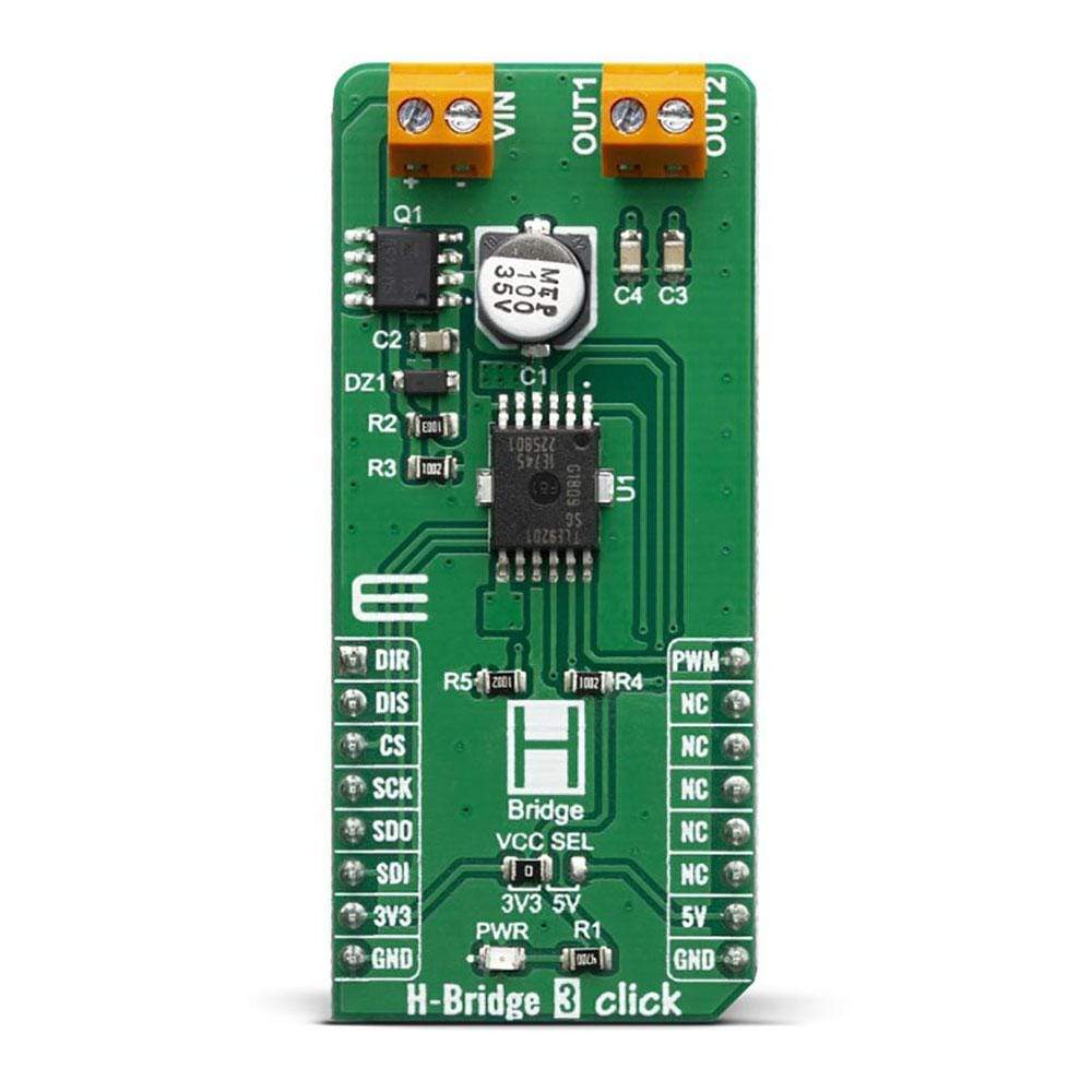
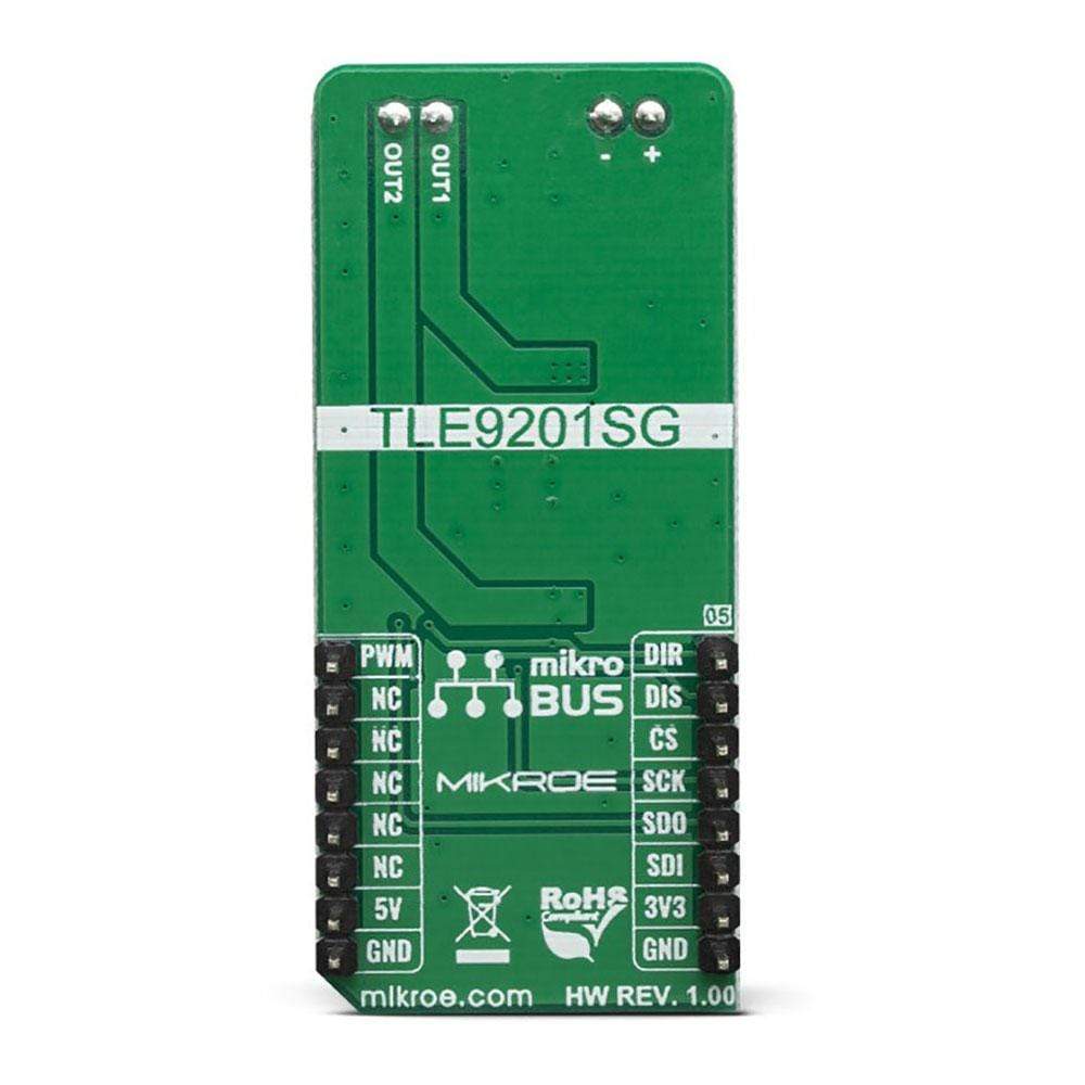
The H-Bridge 3 Click Board™ is designed for the control of small DC motors and inductive loads, it features TLE9201SG a general-purpose 6A H-Bridge perfectly suited for industrial and automotive applications. This IC meets the harsh automotive environmental conditions and it is qualified in accordance with the AEC-Q100 standard, also has a set of features such as the short circuit and over-temperature protection, under-voltage protection, detailed SPI diagnosis or simple error flag and fully 3.3/5.5V compatible logic inputs.
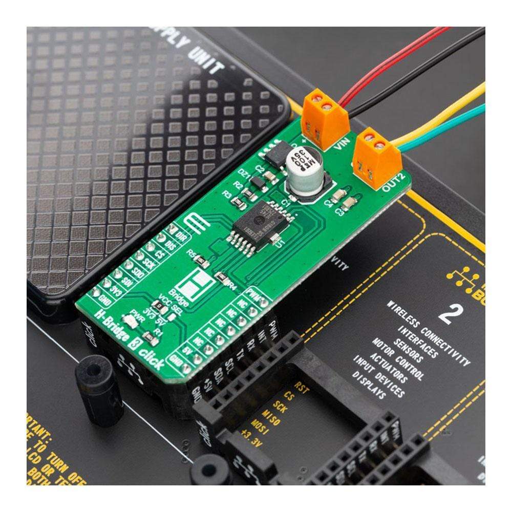
The H-Bridge 3 Click Board™ is supported by a mikroSDK compliant library, which includes functions that simplify software development. This Click Board™ comes as a fully tested product, ready to be used on a system equipped with the mikroBUS™ socket.
Downloads
Le H-Bridge 3 Click Board™ est conçu pour le contrôle de petits moteurs à courant continu et de charges inductives. Il est doté du TLE9201SG, un pont en H 6 A à usage général parfaitement adapté aux applications industrielles et automobiles. Ce circuit intégré répond aux conditions environnementales difficiles de l'automobile et est qualifié conformément à la norme AEC-Q100. Il dispose également d'un ensemble de fonctionnalités telles que la protection contre les courts-circuits et les surchauffes, la protection contre les sous-tensions, le diagnostic SPI détaillé ou le simple indicateur d'erreur et des entrées logiques entièrement compatibles 3,3/5,5 V.
Le H-Bridge 3 Click Board™ est pris en charge par une bibliothèque compatible mikroSDK, qui comprend des fonctions qui simplifient le développement logiciel. Ce Click Board™ est un produit entièrement testé, prêt à être utilisé sur un système équipé du socket mikroBUS™.
| General Information | |
|---|---|
Part Number (SKU) |
MIKROE-3613
|
Manufacturer |
|
| Physical and Mechanical | |
Weight |
0.021 kg
|
| Other | |
EAN |
8606018716159
|
Frequently Asked Questions
Have a Question?
Be the first to ask a question about this.