


Mikroelektronika d.o.o.
Carte à clic STSPIN233
Carte à clic STSPIN233
SKU: MIKROE-3546
Impossible de charger la disponibilité du service de retrait
Overview
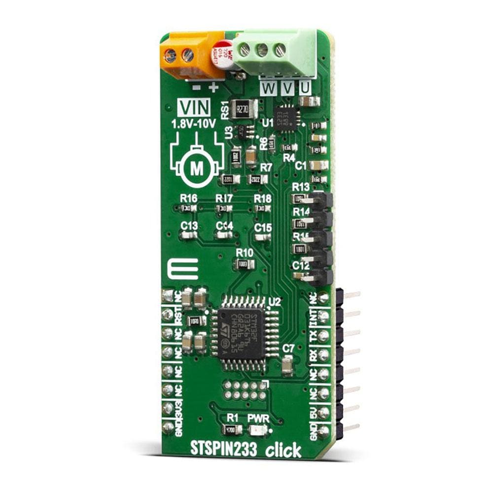
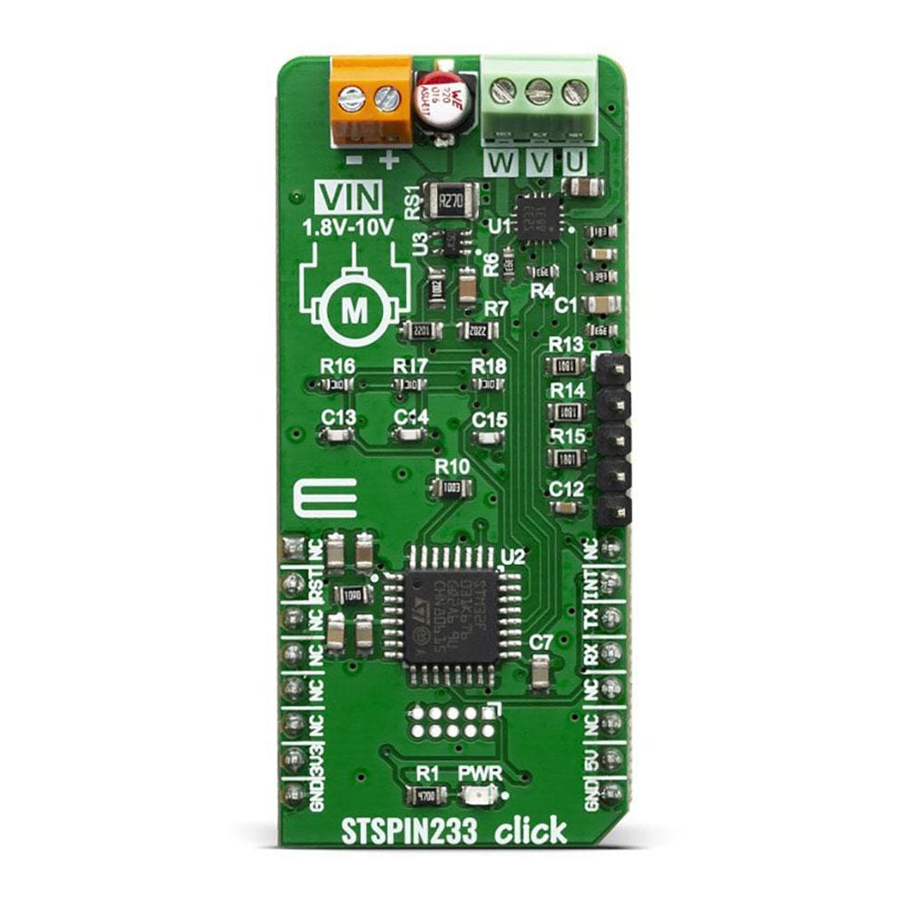
The STSPIN233 Click Board™ is a complete solution for a 3-phase integrated motor driver, based on the STSPIN233, Low voltage 3-phase integrated motor driver. It is optimized for battery-powered, low voltage motor driving applications, featuring the lowest standby current available on the market (max 80 nA).
The STSPIN233 is a high-efficiency motor driver, featuring low ON resistance MOSFETs as the output stage, and extremely low leakage current (max 1µA). Its output stage implements the PWM current control with fixed OFF time, along with a full set of protection features. The device can be used with the step motor voltage ranging from 1.8V to 10V, and current up to 1.3A per bridge.
Downloads
Le STSPIN233 Click Board™ est une solution complète pour un pilote de moteur intégré triphasé, basée sur le STSPIN233, un pilote de moteur intégré triphasé basse tension. Il est optimisé pour les applications de pilotage de moteurs basse tension alimentés par batterie, avec le courant de veille le plus faible disponible sur le marché (max 80 nA).
Le STSPIN233 est un pilote de moteur à haut rendement, doté de MOSFET à faible résistance à l'état passant comme étage de sortie et d'un courant de fuite extrêmement faible (max 1 µA). Son étage de sortie implémente le contrôle de courant PWM avec un temps d'arrêt fixe, ainsi qu'un ensemble complet de fonctions de protection. L'appareil peut être utilisé avec une tension de moteur pas à pas allant de 1,8 V à 10 V et un courant jusqu'à 1,3 A par pont.
| General Information | |
|---|---|
Part Number (SKU) |
MIKROE-3546
|
Manufacturer |
|
| Physical and Mechanical | |
Weight |
0.018 kg
|
| Other | |
EAN |
8606018715725
|
Frequently Asked Questions
Have a Question?
Be the first to ask a question about this.