


Mikroelektronika d.o.o.
Carte à clic MUX 2
Carte à clic MUX 2
SKU: MIKROE-3245
Impossible de charger la disponibilité du service de retrait
Overview
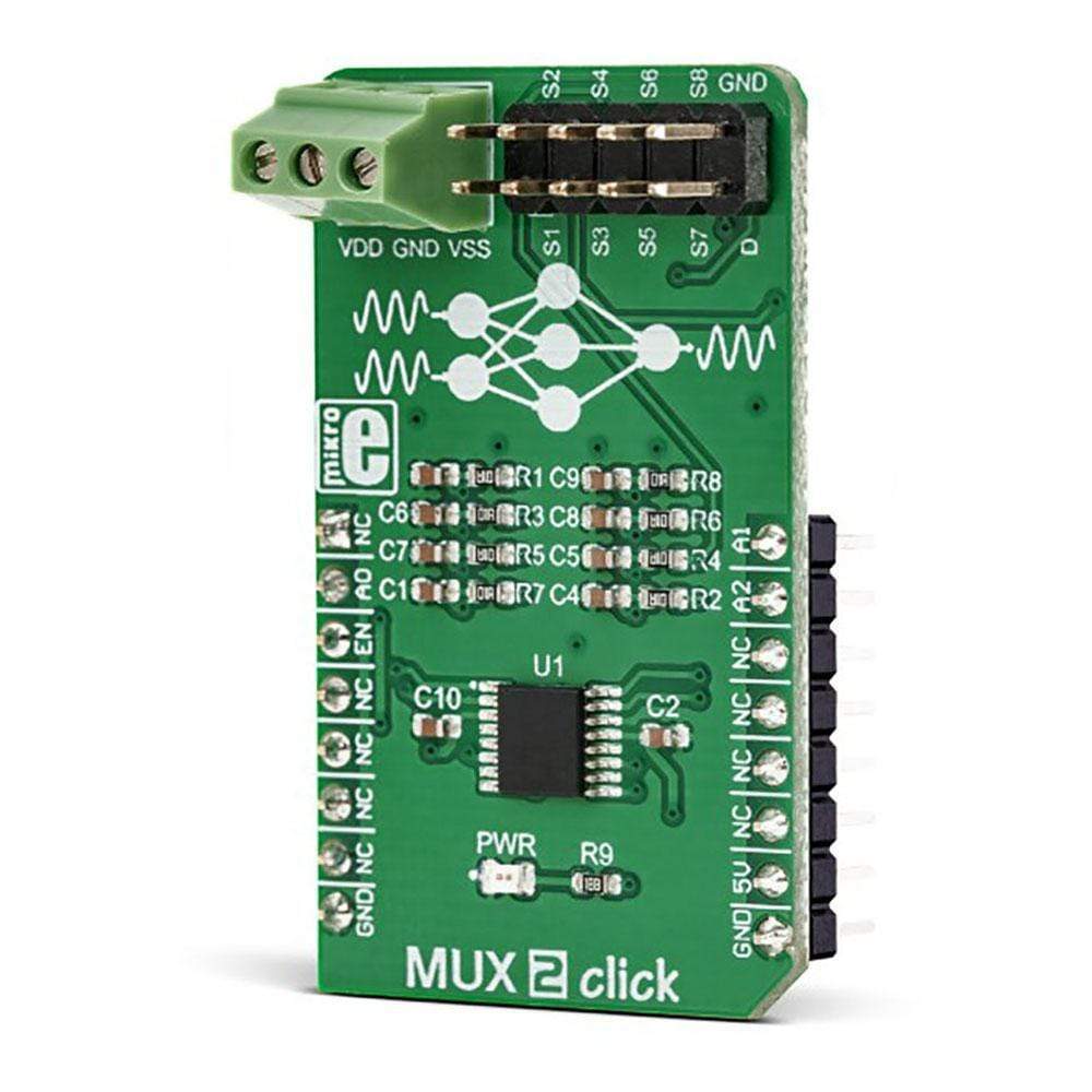
The MUX 2 Click Board™ switches one of the eight inputs to one output. It employs the MUX508, a modern CMOS analogue multiplexing integrated circuit, produced by Texas Instruments. This IC can be powered with both dual power supplies, ranging from ±5V to ±18V, and single power supplies, ranging from 10V to 36V. It offers the rail-to-rail operation, allowing the input signal to swing up (and down) to the voltage of the power supply, with no distortion. Features such as the break-before-make switching action, electrostatic discharge protection up to 2kV, low on-resistance and low input current leakage, make this circuit a perfect solution for various switching applications, operating with both unipolar and bipolar signals.
It comes in a package that also includes the mikroSDK software and a library with all the functions. The MUX 2 Click Board™ comes as a fully tested and approved prototype, making it a reliable device ready to use on the development board.
Downloads
Le MUX 2 Click Board™ commute l'une des huit entrées vers une sortie. Il utilise le MUX508, un circuit intégré de multiplexage analogique CMOS moderne, produit par Texas Instruments. Ce circuit intégré peut être alimenté à la fois par des alimentations doubles, allant de ±5 V à ±18 V, et par des alimentations simples, allant de 10 V à 36 V. Il offre un fonctionnement rail à rail, permettant au signal d'entrée de monter (et de descendre) en fonction de la tension de l'alimentation, sans distorsion. Des caractéristiques telles que l'action de commutation avant fermeture, la protection contre les décharges électrostatiques jusqu'à 2 kV, une faible résistance à l'état passant et une faible fuite de courant d'entrée font de ce circuit une solution parfaite pour diverses applications de commutation, fonctionnant avec des signaux unipolaires et bipolaires.
Il est livré dans un package qui comprend également le logiciel mikroSDK et une bibliothèque avec toutes les fonctions. Le MUX 2 Click Board™ est livré sous la forme d'un prototype entièrement testé et approuvé, ce qui en fait un appareil fiable prêt à être utilisé sur la carte de développement.
| General Information | |
|---|---|
Part Number (SKU) |
MIKROE-3245
|
Manufacturer |
|
| Physical and Mechanical | |
Weight |
0.02 kg
|
| Other | |
EAN |
8606018713912
|
Frequently Asked Questions
Have a Question?
Be the first to ask a question about this.