


Mikroelektronika d.o.o.
Carte à clic pour micro-ondes 2 (UE)
Carte à clic pour micro-ondes 2 (UE)
SKU: MIKROE-3187
Impossible de charger la disponibilité du service de retrait


Key Features
Overview
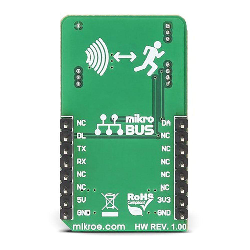
The Microwave 2 Click Board™ is an accurate and reliable short to medium range motion detection Click Board™, based on a Doppler radar principle. Thanks to the highly integrated NJR4265RF2C1, an intelligent 24GHz microwave motion sensor, it can accurately sense the movement of a low-speed object. Featuring an integrated RF circuit, IF amplifier, and the MCU with its accompanying circuitry, it is able to provide signal processing, allowing better isolation of the useful movement signal and reduction of the background noise. In addition, it can detect an object approaching or leaving away, and autonomously signalize the detected event.
Note: The Microwave 2 Click Board™ is available for all EU regions.
Downloads
Le Microwave 2 Click Board™ est un Click Board™ de détection de mouvement à courte et moyenne portée précis et fiable, basé sur un principe de radar Doppler. Grâce au NJR4265RF2C1 hautement intégré, un capteur de mouvement à micro-ondes intelligent de 24 GHz, il peut détecter avec précision le mouvement d'un objet à faible vitesse. Doté d'un circuit RF intégré, d'un amplificateur IF et du MCU avec ses circuits associés, il est capable de fournir un traitement du signal, permettant une meilleure isolation du signal de mouvement utile et une réduction du bruit de fond. De plus, il peut détecter un objet qui s'approche ou s'éloigne et signaler de manière autonome l'événement détecté.
Remarque : le Microwave 2 Click Board™ est disponible pour toutes les régions de l'UE.
| General Information | |
|---|---|
Part Number (SKU) |
MIKROE-3187
|
Manufacturer |
|
| Physical and Mechanical | |
Weight |
0.022 kg
|
| Other | |
EAN |
8606018713615
|
Frequently Asked Questions
Have a Question?
Be the first to ask a question about this.