


Mikroelektronika d.o.o.
Tableau de clic du conducteur
Tableau de clic du conducteur
SKU: MIKROE-3109
Impossible de charger la disponibilité du service de retrait

Overview
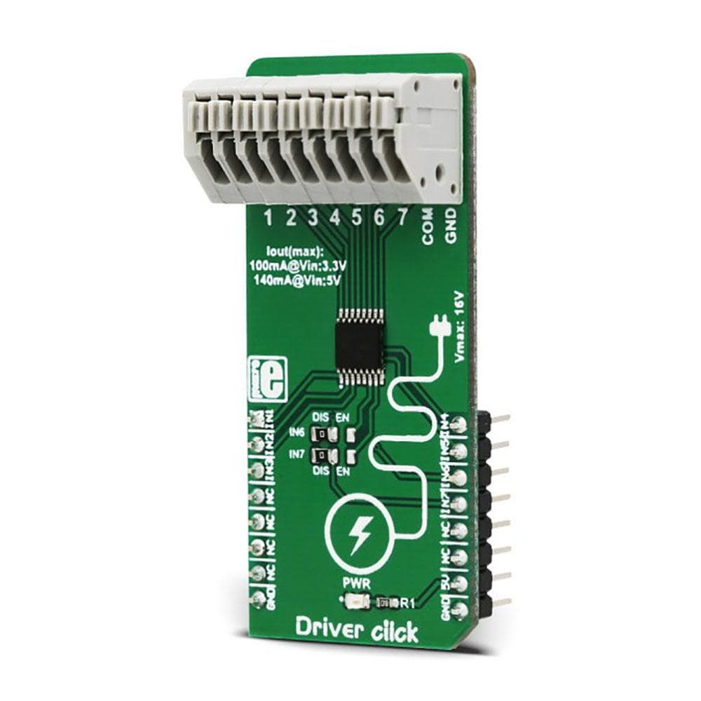
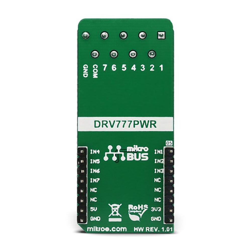
The Driver Click Board™ features an IC with seven integrated high-current sink drivers, which can be used to drive a wide range of loads via a simple parallel interface. These integrated drivers use high-efficiency MOSFETs for improved thermal performance. The DRV777 integrated motor and relay driver IC from Texas Instruments is the main active element of this Click Board™.
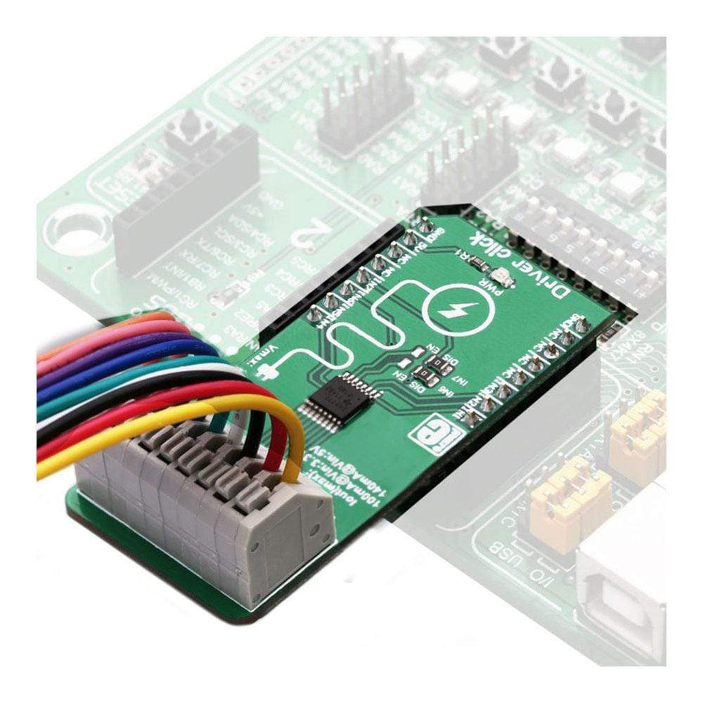
It is ideally suited for driving motors, relays, and similar inductive loads, as it features an internal free-wheeling diode for inductive kickback protection, on every channel. It operates with voltages up to 20 V, and by combining all the channels, it can sink up to 1A of current.
Downloads
Le Driver Click Board™ est doté d'un circuit intégré avec sept pilotes de courant élevé intégrés, qui peuvent être utilisés pour piloter une large gamme de charges via une simple interface parallèle. Ces pilotes intégrés utilisent des MOSFET à haut rendement pour des performances thermiques améliorées. Le circuit intégré de pilote de moteur et de relais intégré DRV777 de Texas Instruments est le principal élément actif de ce Click Board™.
Il est parfaitement adapté à la commande de moteurs, de relais et de charges inductives similaires, car il dispose d'une diode de roue libre interne pour la protection contre les contrecoups inductifs, sur chaque canal. Il fonctionne avec des tensions allant jusqu'à 20 V et, en combinant tous les canaux, il peut absorber jusqu'à 1 A de courant.
| General Information | |
|---|---|
Part Number (SKU) |
MIKROE-3109
|
Manufacturer |
|
| Physical and Mechanical | |
Weight |
0.023 kg
|
| Other | |
EAN |
8606018713349
|
Frequently Asked Questions
Have a Question?
Be the first to ask a question about this.