Carte de pilote LED 3 clics
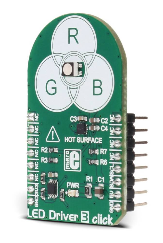
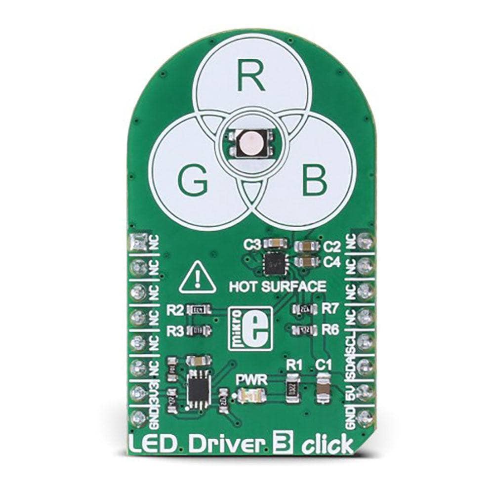
Le LED Driver 3 Click Board™ est un driver LED RGB, capable de piloter des LED RGB jusqu'à 30 mA par segment, via l'interface numérique I2C. Il est équipé d'une LED RGB intégrée et est capable d'afficher une palette de 32 768 couleurs. Il dispose d'un circuit intégré avec trois sections de driver LED indépendantes et d'un contrôle de gradation progressif programmable, qui donne un effet de gradation fluide. La dissipation de chaleur est réduite au minimum, du fait que le circuit intégré de driver utilisé fonctionne avec une efficacité allant jusqu'à 94 %.
The LED Driver 3 Click Board™ is an RGB LED driver, capable of driving RGB LEDs with up to 30mA per segment, via the digital I2C interface. It comes with an RGB LED onboard, and is capable of displaying a palette of 32768 colors. It features an integrated circuit with three independent LED driver sections and a programmable gradual dimming control, which gives a smooth dimming effect. Heat dissipation is taken to the minimum, due to a fact that the used driver IC works with up to 94% efficiency.
The LED Driver 3 Click Board™ can be used in a range of different applications: color backlight displays, backlit computer keyboards and mice, color-coded signalization, and in many decorative colored lighting applications, which can be controlled by an MCU.
How Does The LED Driver 3 Click Board™ Work?
The main component of the LED Driver 3 Click Board™ is the NCP5623B, a triple output RGB LED driver, controlled through the I2C protocol, from ON Semiconductors. This IC is equipped with an internal DC/DC converter, that works as a high-efficiency charge pump, providing the required DC voltage for all three LED segments. The current flow through each LED segment is regulated by an internal current mirror, associated with each of the channels.
The gradual dimming function allows an easy way of dimming RGB LED intensity. With a simple I2C command, it is possible to trigger either upward or downward dimming. Dimming will affect the current through the LED segments, but the internal current limiter takes care not to exceed the maximum allowed current, set by the onboard resistor.
The integrated PWM operates with five bits, having 32 steps to cover the full modulation (0 to 100%) of the associated LED channel. Having a value of 0x00h will turn the associated LED completely OFF, while 0x1Fh will set the LED to a programmed LED current value. The last three bits (MSB) are used to set the desired command register: PWM1, PWM2, PWM3, dimming direction, gradual dimming, LED current, etc. It should be noted that the gradual dimming function affects the illumination by changing the LED current intensity, while PWM affects the associated LED illumination by changing the pulse width - e.g. it is possible to set the desired color by setting the PWM modulation of each color component, and then gradually dim the brightness of the final color mix up or down by the gradual dimming option - affecting the current through all the LED segments simultaneously. It is also possible to set the fixed value for the current through the LED segments via the I2C interface, when gradual dimming is not needed.
More information about the registers and their usage can be found in the NCP5623B datasheet. However, the provided click library offers easy to use functions for setting up the RGB color of the LED and utilizing the smooth gradient functions. The included example application demonstrates the functionality and usage of these libraries. The example can be used as a reference for custom projects.
To allow operation on both 3.3V and 5V MCUs, LED Driver 3 click employs PCA9306, a dual bidirectional I2C/SMBUS voltage level translator from Texas Instruments. This IC allows the click board to be interfaced with both 3.3V and 5V MCUs. The logic voltage level shifting is done automatically, so no SMD jumpers are needed in this case. Both 3.3V and 5V rails are needed for this circuit to be operational.
The LED Driver 3 Click Board™ is also equipped with an RGB LED. This is a high brightness RGB LED with a wide viewing angle, that can get very hot and bright while operated with maximum current. For this reason, a care must be taken not to touch it or watch directly at the LED.
SCL1 and SDA1 lines from the I2C level shifter are routed to the standard mikroBUS™ I2C pins, labeled as SCL and SDA. The click board™ already contains pull-up resistors, so no additional parts are needed to work with the click board.
SPECIFICATIONS
Type | LED Drivers |
Applications | The LED Driver 3 Click Board™ can be used for color backlight displays, backlit computer keyboards and mice, color-coded signalization, and in many decorative colored lighting applications, which can be controlled by the MCU. |
On-board modules | NCP5623B, a triple output RGB LED driver, controlled through the I2C protocol, from ON Semiconductors. |
Key Features | The LED Driver 3 Click Board™ features an integrated circuit with three independent LED driver sections and a programmable gradual dimming control, which gives a smooth dimming effect. It can display 32768 different colors. |
Interface | I2C |
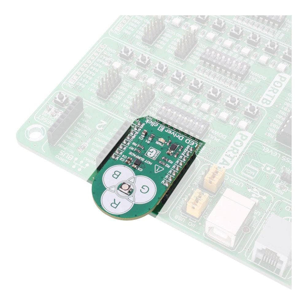
Compatibility | mikroBUS |
Click board size | M (42.9 x 25.4 mm) |
Input Voltage | 3.3V,5V |
PINOUT DIAGRAM
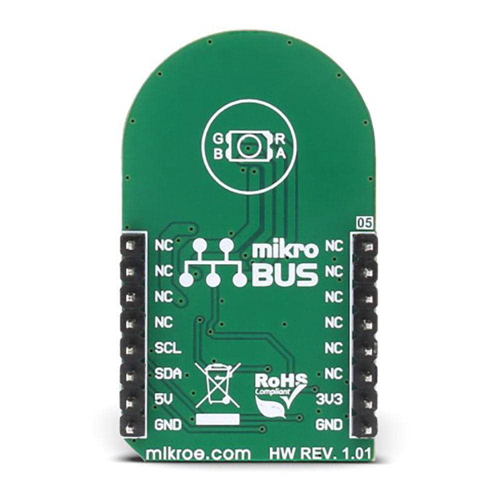
This table shows how the pinout on the LED Driver 3 Click Board™ corresponds to the pinout on the mikroBUS™ socket (the latter shown in the two middle columns).
Notes | Pin | Pin | Notes | ||||
---|---|---|---|---|---|---|---|
NC | 1 | AN | PWM | 16 | NC | ||
NC | 2 | RST | INT | 15 | NC | ||
NC | 3 | CS | RX | 14 | NC | ||
NC | 4 | SCK | TX | 13 | NC | ||
NC | 5 | MISO | SCL | 12 | SCL | I2C Clock | |
NC | 6 | MOSI | SDA | 11 | SDA | I2C Data | |
Power Supply | +3V3 | 7 | 3.3V | 5V | 10 | +5V | Power Supply |
Ground | GND | 8 | GND | GND | 9 | GND | Ground |
ONBOARD SETTINGS AND INDICATORS
Label | Name | Default | Description |
---|---|---|---|
LD1 | PWR | - | Power indication LED |
Software Support
We provide a library for the LED Driver 3 Click Board™ on our Libstock page, as well as a demo application (example), developed using MikroElektronika compilers and mikroSDK. The provided click library is mikroSDK standard compliant. The demo application can run on all the main MikroElektronika development boards.
Library Description
The library carries functions necessary to have complete control over all functionalities of the LED Driver 3 Click Board™.
Key Functions
void leddriver3_setIntensity(uint8_t intensity)
- Set intensity of LED light.void leddriver3_setRGB_Color(uint8_t red, uint8_t green, uint8_t blue)
- Set color in RGB format.void leddriver3_setColor(uint32_t color)
- Set color using one of the predefined values.
Example Description
The demo application is composed of three sections:
- System Initialization - Initializes I2C module used for the LED Driver 3 Click Board™.
- Application Initialization - Driver initialization.
- Application Task - (code snippet) - Sequentially changes intensity and color of the LED light with delays of one second between each operation.
void applicationTask() { leddriver3_setIntensity(_LEDDRIVER3_INCREMENT | _LEDDRIVER3_INTENSITY_8); leddriver3_setTimer(_LEDDRIVER3_TIMER_8ms | _LEDDRIVER3_TIMER_16ms); // 24 ms leddriver3_setColor(_LEDDRIVER3_COLOR_RED); Delay_1sec(); leddriver3_setIntensity(_LEDDRIVER3_CONSTANT | _LEDDRIVER3_INTENSITY_16); leddriver3_setColor(_LEDDRIVER3_COLOR_YELLOW); Delay_1sec(); leddriver3_setColor(_LEDDRIVER3_COLOR_BLUE); Delay_1sec(); leddriver3_setRGB_Color(0x40, 0x7F, 0x80); Delay_1sec(); }
The full application code, and ready to use projects can be found on our Libstock page.
Other mikroE Libraries used in the example:
- I2C
Additional Notes and Information
Depending on the development board you are using, you may need USB UART click, USB UART 2 click or RS232 click to connect to your PC, for development systems with no UART to USB interface available on the board. The terminal available in all MikroElektronika compilers, or any other terminal application of your choice, can be used to read the message.
MIKROSDK
The LED Driver 3 Click Board™ is supported with mikroSDK - MikroElektronika Software Development Kit. To ensure proper operation of mikroSDK compliant click board demo applications, mikroSDK should be downloaded from the LibStock and installed for the compiler you are using.
Carte de pilote LED 3 clics
Frequently Asked Questions
Have a Question?
Be the first to ask a question about this.