Passer aux informations produits
1 de 5

Mikroelektronika d.o.o.

Carte à clic DIGI POT 5

Carte à clic DIGI POT 5

SKU: MIKROE-2863
Prix habituel
€16,95 EUR hors taxes
Prix habituel Prix promotionnel
€16,95 EUR hors taxes
En vente Épuisé
Frais d'expédition calculés à l'étape de paiement.
If no stock shown above, check availability
Afficher tous les détails

Overview

Le DIGI POT 5 Click Board™ est un potentiomètre quadruple à commande numérique, avec une résistance de 10Kohm. Il possède une résolution de pas de curseur de 8 bits, ce qui permet au curseur de prendre 257 positions discrètes différentes (sur 256 résistances internes). La position du curseur numérique peut être contrôlée via l'interface SPI.

Le DIGI POT 5 Click Board™ est doté d'une mémoire EEPROM non volatile (NV) durable pour stocker la position de l'essuie-glace. Le contenu de la mémoire du registre d'essuie-glace situé dans la mémoire NV est copié dans les registres d'essuie-glace réels après la mise sous tension ou la réinitialisation, de sorte que l'appareil agit de manière similaire à son homologue mécanique, rappelant sa dernière position d'essuie-glace utilisée après la mise sous tension. L'appareil est également doté de la technologie WiperLock, qui verrouille efficacement la position de l'essuie-glace en place.

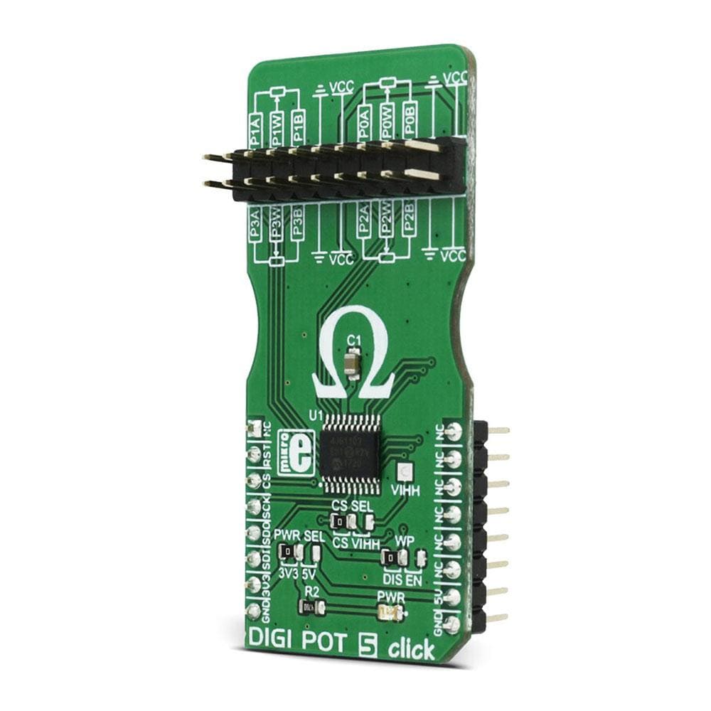
The DIGI POT 5 Click Board™ is a digitally controlled quad potentiometer, with the resistance of 10KΩ. It has an 8bit wiper step resolution, which allows the wiper to take 257 different discrete positions (across 256 internal resistors). The digital wiper position can be controlled via the SPI interface. The DIGI POT 5 Click Board™ features a durable EEPROM non-volatile (NV) memory for storing the wiper position. The content of the wiper register memory located in the NV memory is copied to the actual wiper registers after the power-on or reset state, so the device acts similar to its mechanical counterpart, recalling its last used wiper position after being powered on. The device also features the WiperLock™ technology, which effectively locks the wiper position in place.

The DIGI POT 5 Click Board™ has a multitude of practical uses in electronic circuits. The most popular uses include precision calibration of set point thresholds, sensor trimming, LCD contrast adjustment, audio attenuation, an adjustable gain for amplifiers and offset trimming. DIGI POT 5 click can be used to replace the common mechanical trim pot, in a wide range of different applications where the operating voltage stays within the limits.

How Does The DIGI POT 5 Click Board™ Work?

The DIGI POT 5 Click Board™ features the MCP4361, an 8bit quad digital potentiometer from Microchip. This is a very versatile quad digital potentiometer, controlled via the SPI interface. The device has four integrated digital potentiometer sections, which consist of a string of resistors - serially connected, with digitally controlled analog switches, used to connect the wiper terminal position. The wiper position value of 0x000h corresponds to the lower end of the resistors ladder, while 0x100h corresponds to the upper end of the resistors ladder. These values can be written in the volatile wiper registers, one address for each of the four wipers.

Each of the four wipers can be controlled in several ways. Writing data directly to the volatile wiper register will result in moving the wiper to the specified location. Wiper value can also be incremented or decremented, by writing data to the incrementing or decrementing registers, providing that the wiper is not locked and that the wiper register value is not 0x000h (prevents further decrease) or above 0x100h (prevents further increase). If the wiper register is set to a value greater than 0x100h, both increasing and decreasing commands will be disregarded. The incrementing and decrementing registers allow for less overhead if the wiper position has to be increased or decreased, making it easy to interface with the rotary encoder applications, for example.

The MCP4361 also features the WiperLock™ function, which prevents further changes of the wiper position, effectively locking the wiper in place. To enable this functionality, the CS pin needs to be pulled beyond the predefined voltage level threshold (8.5V to 12.5V). When this happens, the device will enter into the high voltage communication mode (HV mode), and the WiperLock™ functions can be accessed. The click board has a dedicated high voltage input pad (VIHH), which can be used to drive the CS pin with the appropriate voltage level when the HV mode is required.

The resistor ladder network can be completely disabled by writing to the terminal control registers. This allows to effectively disconnect the potentiometer terminals from a circuit, reducing the power consumption of both the MCP4361 and the electrical circuit the IC is used in. The terminal control registers can also be used to switch each of the wiper terminal and the two resistor terminals, separately. There is also a STATUS register, used for storing various status related information, such as the WiperLock™ status, EEPROM write protect status and so on.

The EEPROM memory is used to hold the wiper data, even after the power down. There are several (five) general purpose 9bit addresses and 4 NV wiper register addresses that are copied to the wiper register addresses after the restart or power-up, allowing the device to resume the wiper position from a previous, stored state. By default, the data registers are zeroed out, while the NV wiper registers hold the middle scale position for the wiper.

The DIGI POT 5 Click Board™ has one 2x10 pin standard, 2.54mm pitch header used to connect the four potentiometer terminals. There are three SMD jumpers onboard:

The SMD jumper labelled as WP is used to set the WP pin state of the MCP4361. The WP pin is used as the hardware EEPROM write protection, along with a software WP bit of the STATUS register (writable in HV mode only). Both the hardware WP pin and the software WP bit has to be set to disabled mode, in order to write to EEPROM.

The SMD jumper labelled as PWR SEL is used to select the power supply voltage - 3.3V or 5V. This also affects the logic voltage levels, used for the SPI communication.

The SMD jumper labelled as CS SEL is used to select the CS pin voltage level. If the HV mode is required, this jumper should be moved to the VIHH position, so that the externally connected 8.5V to 12.5V power source can be used to pull up the CS pin. If HV mode is not required, this SMD jumper should stay at the default position (CS). Note that while in the HV mode, the CS pin is used the same way as with the regular SPI communication, with a difference in logical levels - the HV mode logical HIGH is at least 8.5V.

SPECIFICATIONS

Type Digital potentiometer
Applications The DIGI POT 5 Click Board™ can be used for precise calibration of set point thresholds, sensor trimming, LCD contrast adjustment, audio attenuation, an adjustable gain for amplifiers and offset trimming
On-board modules MCP4361 8-Bit quad digital POT with non-volatile Memory and SPI interface
Key Features Digitally controlled quad potentiometer with 257 discrete wiper positions, SPI communication protocol, WiperLock™ feature, and user programmable EEPROM memory
Interface GPIO,SPI
Compatibility mikroBUS
Click board size L (57.15 x 25.4 mm)
Input Voltage 3.3V or 5V

PINOUT DIAGRAM

This table shows how the pinout of the DIGI POT 5 Click Board™ corresponds to the pinout on the mikroBUS™ socket (the latter shown in the two middle columns).

Notes Pin Mikrobus logo.png Pin Notes
NC 1 AN PWM 16 NC
Reset RST 2 RST INT 15 NC
SPI CS CS 3 CS RX 14 NC
SPI Clock SCK 4 SCK TX 13 NC
SPI Data Out SDO 5 MISO SCL 12 NC
SPI Data In SDI 6 MOSI SDA 11 NC
Power Supply +3.3V 7 3.3V 5V 10 +5V Power Supply
Ground GND 8 GND GND 9 GND Ground

DIGI POT 5 CLICK ELECTRICAL SPECIFICATIONS

Description Min Typ Max Unit
Resistance (PxA to PxB) 8 10 12 kΩ
Wiper resistance - 75 300
Pot terminals input voltage range GND - VDD V
Pot terminals maximum current -2.5 - 2.5 mA
CS HV mode HIGH logic level (on VIHH pad) 8.5 - 12.5 V

ONBOARD SETTINGS AND INDICATORS

Label Name Default Description
LD1 PWR - Power LED indicator
JP1 PWR SEL Left Power supply voltage selection: left position 3V3, right position 5V
JP2 WP Left Write protect selection: left position DISABLED, right position ENABLED
JP3 CS SEL Left CS mode selection: left position CS (SPI), right position VIHH (HV)

Note: When the high voltage mode (HV) is selected, the VIHH pad is used to drive the CS pin with the HIGH logic level ranging from 8.5V to 12.5V.


Frequently Asked Questions

Have a Question?

Be the first to ask a question about this.

Ask a Question

Customer Reviews

Be the first to write a review
0%
(0)
0%
(0)
0%
(0)
0%
(0)
0%
(0)