


Mikroelektronika d.o.o.
Tableau coulissant à clic
Tableau coulissant à clic
SKU: MIKROE-2702
Impossible de charger la disponibilité du service de retrait
Overview
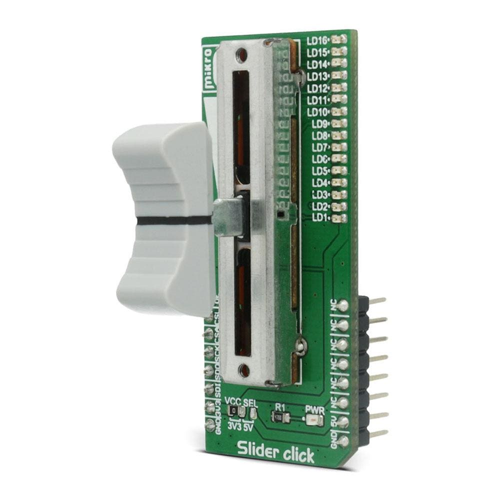
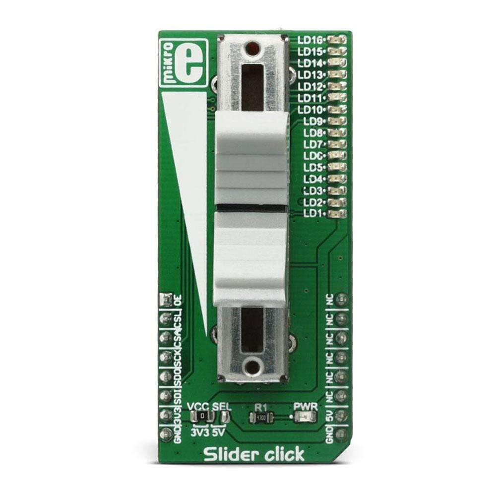
The Slider Click Board™ features a mechanical slide action potentiometer - a slider, which gives a nice feeling when actuating, along with 16 SMD LEDs, that can be used for any kind of visual feedback. The on-board high-resolution 22-bit ADC can detect even the smallest move, faithfully capturing the smoothness of the slider movement, while digitizing its position. The 16 on-board SMD LEDs can give a nice visual feedback of the slider position, but those LEDs can also be used for other purposes since they are not hardwired to the slider.
The Slider Click Board™ can be used to control various digital applications with an accurate and comfortable slider potentiometer, while the LEDs can be used to display the desired information in a form of a bar or a position. For example, Slider Click Board™ can be used to control a quad digital potentiometer, such as the one that can be found on DIGIPOT 5 Click Board™, while displaying the position of the selected digital wiper on the LEDs.
Downloads
Le Slider Click Board™ est doté d'un potentiomètre mécanique à glissière - un curseur, qui donne une sensation agréable lors de l'actionnement, ainsi que de 16 LED SMD, qui peuvent être utilisées pour tout type de retour visuel. Le convertisseur analogique-numérique haute résolution 22 bits intégré peut détecter même le plus petit mouvement, capturant fidèlement la fluidité du mouvement du curseur, tout en numérisant sa position. Les 16 LED SMD intégrées peuvent donner un bon retour visuel de la position du curseur, mais ces LED peuvent également être utilisées à d'autres fins car elles ne sont pas câblées au curseur.
Le Slider Click Board™ permet de contrôler diverses applications numériques avec un potentiomètre à curseur précis et confortable, tandis que les LED permettent d'afficher les informations souhaitées sous forme de barre ou de position. Par exemple, le Slider Click Board™ permet de contrôler un potentiomètre numérique quadruple, tel que celui que l'on retrouve sur le DIGIPOT 5 Click Board™, tout en affichant la position du curseur numérique sélectionné sur les LED.
| General Information | |
|---|---|
Part Number (SKU) |
MIKROE-2702
|
Manufacturer |
|
| Physical and Mechanical | |
Weight |
0.025 kg
|
| Other | |
EAN |
8606018711741
|
Frequently Asked Questions
Have a Question?
Be the first to ask a question about this.