


Key Features
Overview
Le Click Board™ IQRF est basé sur l'émetteur-récepteur RF DCTR-76DA, fonctionnant sur la fréquence 868/916 MHz. Le Click Board™ est conçu pour fonctionner sur une alimentation 3,3 V. Il communique avec le microcontrôleur cible via une interface SPI ou UART, avec des fonctionnalités supplémentaires fournies par les broches suivantes sur la ligne MikroBUS : AN, RST, PWM, INT.
General Information | |
---|---|
Part Number (SKU) |
MIKROE-2586
|
Manufacturer |
|
Physical and Mechanical | |
Weight |
0.018 kg
|
Other | |
Country of Origin |
|
HS Code Customs Tariff code
|
|
EAN |
8606018710355
|
Warranty |
|
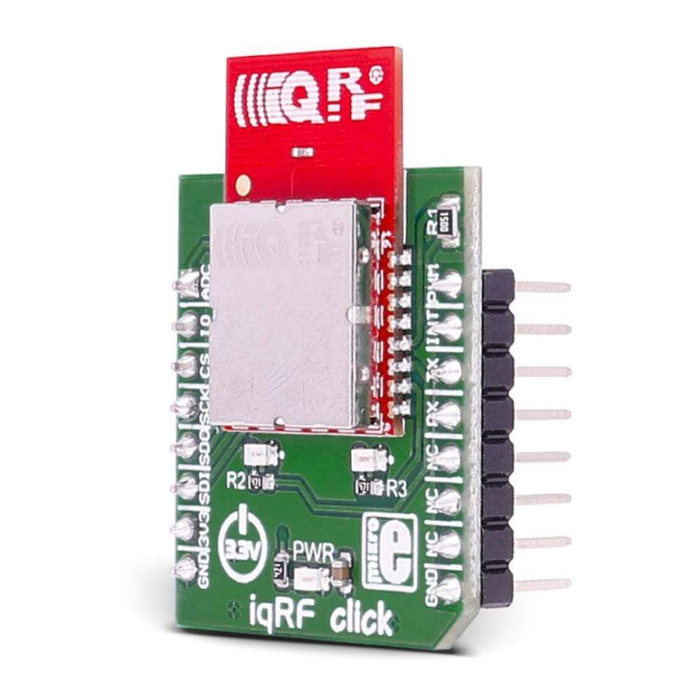
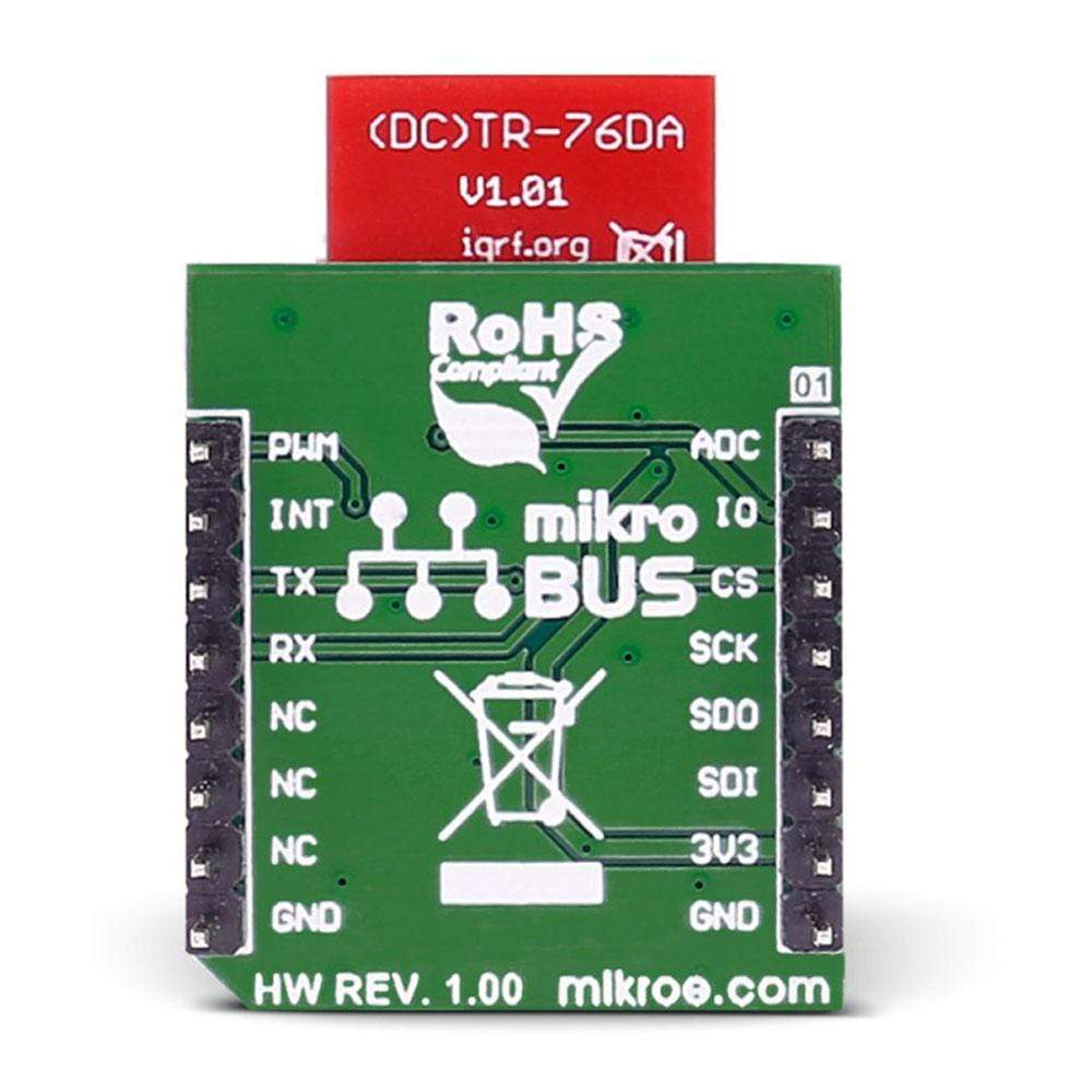
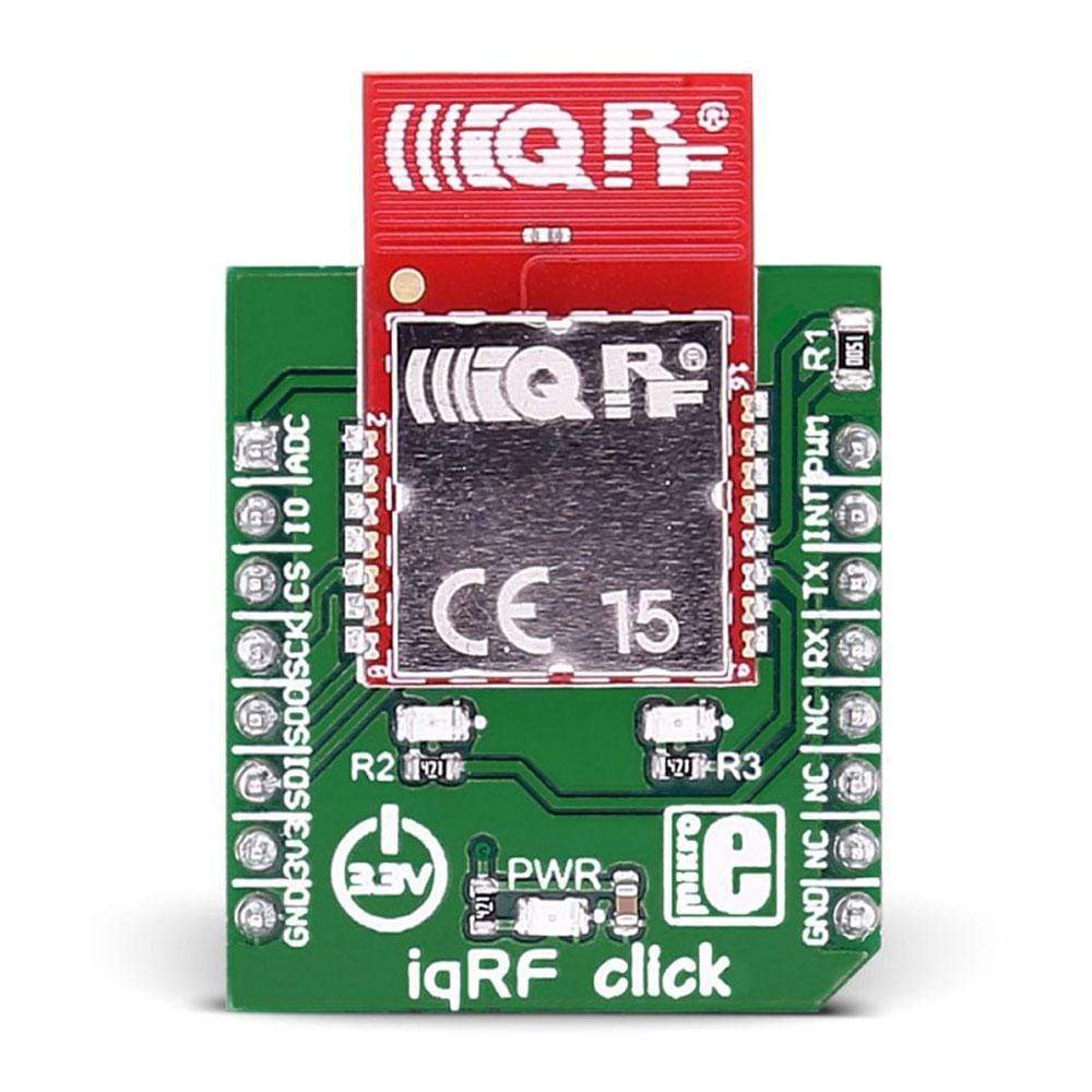
The IQRF Click Board™ is based on the DCTR-76DA RF transceiver, operating in the 868/916 MHz frequency. The click is designed to run on a 3.3V power supply. It communicates with the target microcontroller over SPI or UART interface, with additional functionality provided by the following pins on the mikroBUS™ line: AN, RST, PWM, INT.
Module Features
DTCR-76DA is an RF transceiver operating in the 868/916 MHz license-free ISM (Industry, Scientific, and Medical) frequency band. Its highly integrated ready-to-use design containing MCU, RF circuitry, serial EEPROM and optional onboard antenna requires no external components.
How Does The IQRF Click Board™ Work?
RF transceiver modules DCTR-72DA fit in the SIM connector. They are fully programmable under IQRF OS operating system and allow to utilize hardware profiles under DPA framework.
To upload application codes in DCTRs and configure DCTR parameters, CK-USB-04A kit is intended. When the application is uploaded to the IQRF it can be put in microBUS™ socket and communicate with it with MCU.
Specifications
Type | Sub-1 GHz Transceievers |
Applications | Point-to-point or network wireless connectivity, Telemetry, AMR (automatic meter reading), WSN (wireless sensor network), Building automation, Street lighting control, etc. |
On-board modules | DCTR-76DA RF transceiver |
Key Features | Selectable RF band 868 / 916 MHz, multiple channels |
Interface | Analog,GPIO,SPI,UART |
Compatibility | mikroBUS |
Click board size | S (28.6 x 25.4 mm) |
Input Voltage | 3.3V |
Pinout
This table shows how the pinout on the IQRF Click Board™ corresponds to the pinout on the mikroBUS™ socket (the latter shown in the two middle columns).
Notes | Pin | ![]() |
Pin | Notes | |||
---|---|---|---|---|---|---|---|
Analog pin | ADC | 1 | AN | PWM | 16 | DIN | General I/O pin |
General I/O pin | GPIO | 2 | RST | INT | 15 | INT | Interrupt |
SPI enable | SPI_CS | 3 | CS | TX | 14 | TXD | UART transmit |
SPI Clock | SPI_SCK | 4 | SCK | RX | 13 | RXD | UART receive |
SPI Master Input Slave Output | SPI_MISO | 5 | MISO | SCL | 12 | NC | |
SPI Master Output Slave Input | SPI_MOSI | 6 | MOSI | SDA | 11 | NC | |
Power supply | +3.3V | 7 | 3.3V | 5V | 10 | NC | |
Ground | GND | 8 | GND | GND | 9 | GND | Ground |
Frequently Asked Questions
Have a Question?
Be the first to ask a question about this.