


Mikroelektronika d.o.o.
Carte à clic MCP2517FD
Carte à clic MCP2517FD
SKU: MIKROE-2379
Impossible de charger la disponibilité du service de retrait
Key Features
Overview
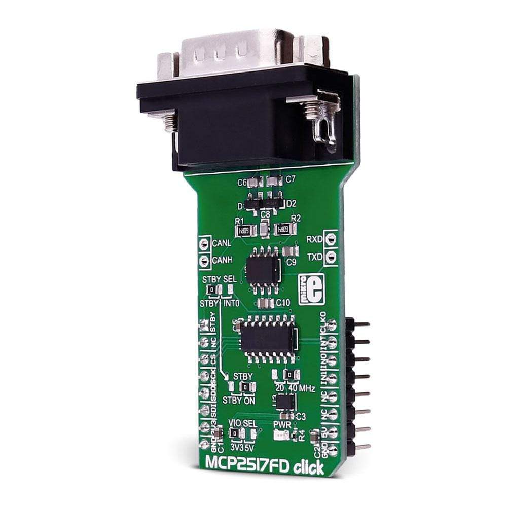
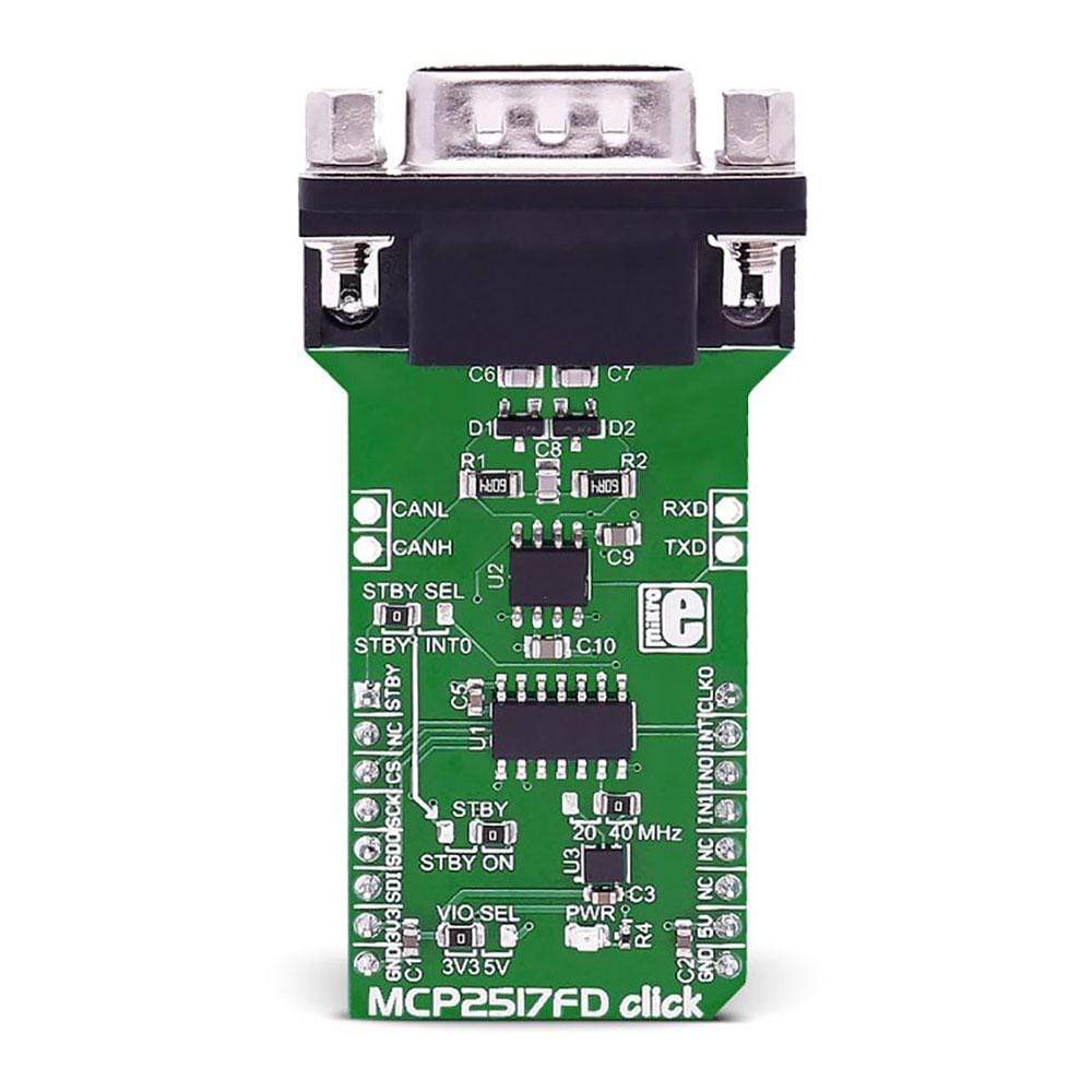
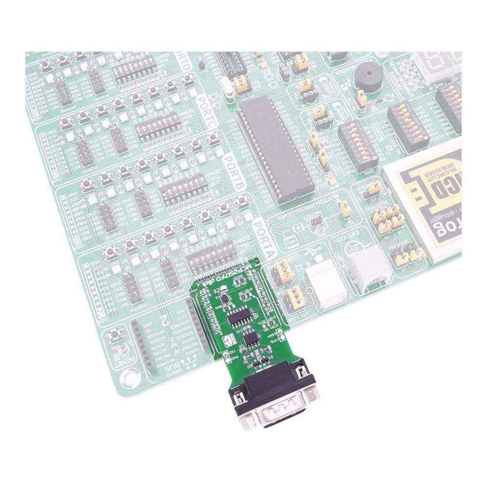
The MCP2517FD Click Board™ is a complete CAN solution that carries the MCP2517FD CAN FD controller and ATA6563 high-speed CAN transceiver from Microchip and a DB9 9-pin connector.
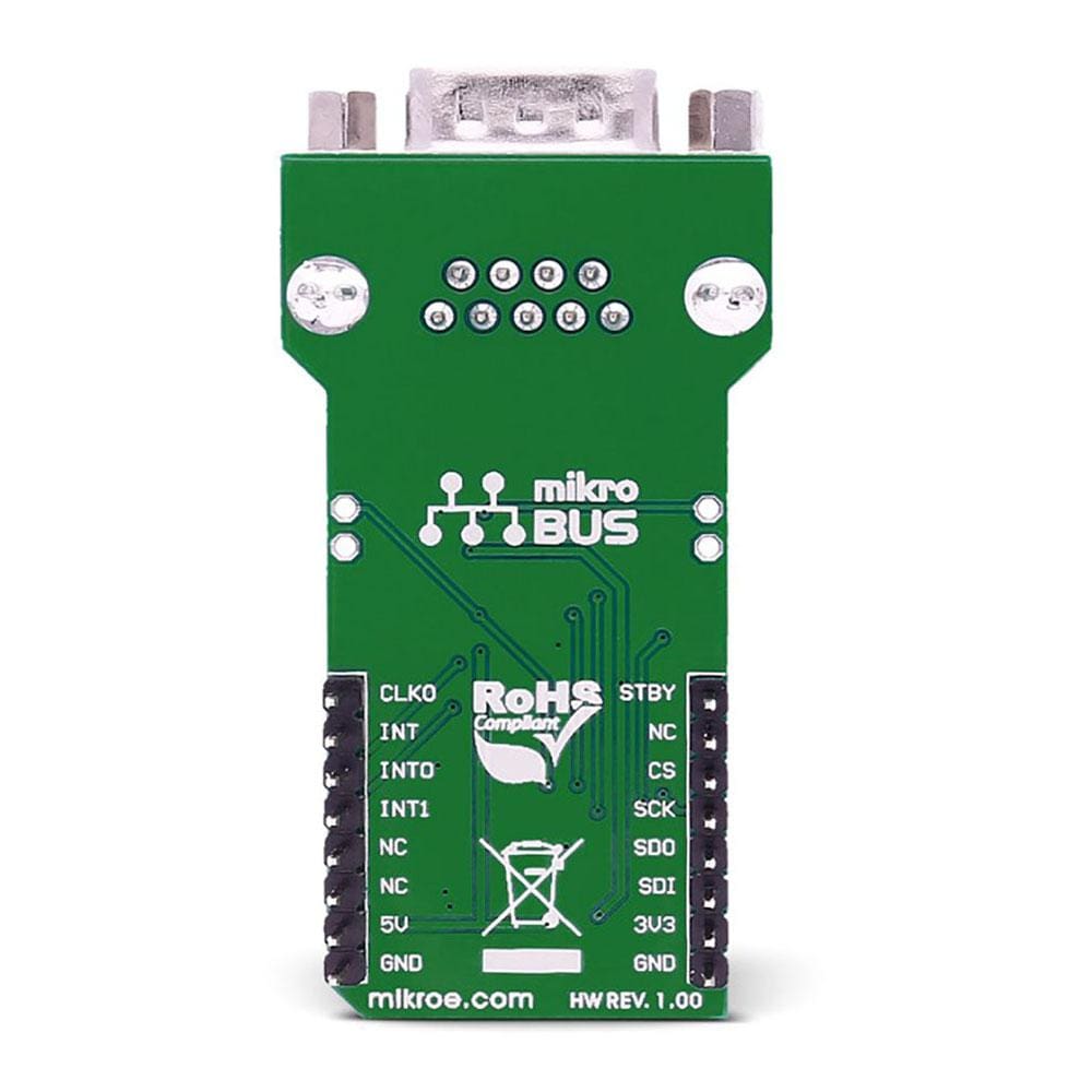
The MCP2517FD Click Board™ Click Board™ requires both 3.3V and 5V power supply. It communicates with the target microcontroller through the SPI interface, with additional functionality provided by the following pins on the MikroBUS socket: AN, PWM, INT, TX and RX.
Downloads
Le MCP2517FD Click Board™ est une solution CAN complète qui intègre le contrôleur CAN FD MCP2517FD et l'émetteur-récepteur CAN haute vitesse ATA6563 de Microchip et un connecteur DB9 à 9 broches.
Le MCP2517FD Click Board™ Click Board™ nécessite une alimentation de 3,3 V et 5 V. Il communique avec le microcontrôleur cible via l'interface SPI, avec des fonctionnalités supplémentaires fournies par les broches suivantes sur la prise MikroBUS : AN, PWM, INT, TX et RX.
| General Information | |
|---|---|
Part Number (SKU) |
MIKROE-2379
|
Manufacturer |
|
| Physical and Mechanical | |
Weight |
0.028 kg
|
| Other | |
EAN |
8606018710447
|
Frequently Asked Questions
Have a Question?
Be the first to ask a question about this.