


Mikroelektronika d.o.o.
Carte à clic 2x2
Carte à clic 2x2
SKU: MIKROE-2152
Impossible de charger la disponibilité du service de retrait


Overview
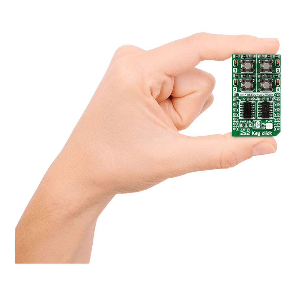
Discover the versatility and functionality of the 2x2 Key Click Board™, a cutting-edge solution for your keypad needs. Designed to offer seamless integration and reliable performance, this innovative board caters to a wide range of applications with its advanced features and intuitive design.
When you choose the 2x2 Key Click Board™, you unlock a world of possibilities. Whether you are a hobbyist or a professional, this versatile keypad solution is tailored to meet your specific requirements with precision and efficiency.
- Experience seamless multi-key functionality with the 2x2 Key Click Board™, designed to support multiple key presses effortlessly.
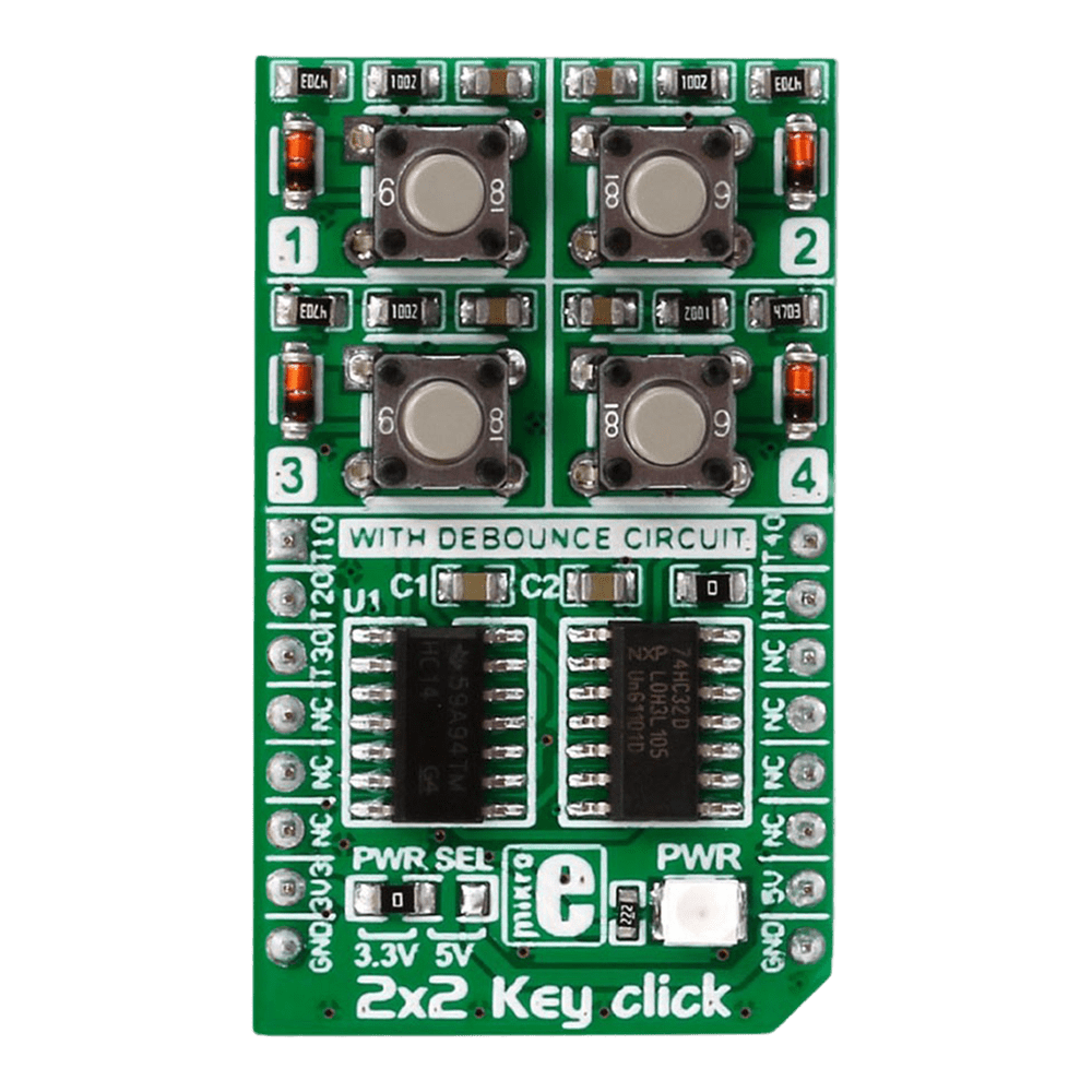
- Benefit from enhanced durability and responsiveness thanks to the debounce circuit featuring top-quality components from leading manufacturers like NXP and Texas Instruments.
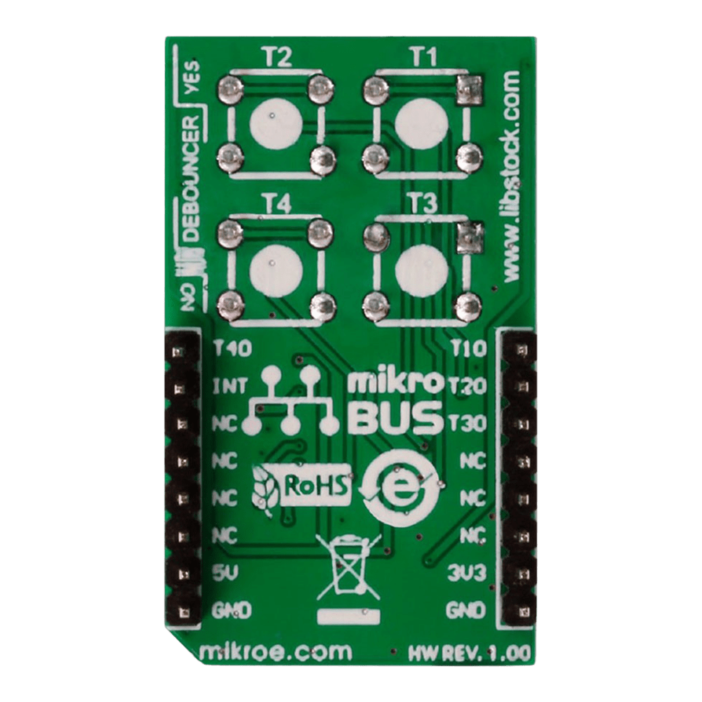
Engineered to adapt to various power supply configurations, the 2x2 Key Click Board™ is compatible with both 3.3V and 5V power sources, ensuring flexibility and convenience in your projects.
With independent button reading capability, this Click Board™ offers enhanced control and precision, allowing you to customise your key inputs according to your specific requirements.
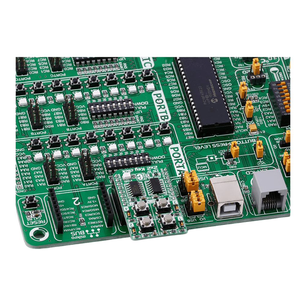
Explore the seamless integration and unparalleled performance of the 2x2 Key Click Board™, a reliable and versatile solution for all your keypad needs. Elevate your projects to new heights with this cutting-edge keypad solution that combines innovation with reliability and efficiency.
Embrace the future of keypad technology with the 2x2 Key Click Board™ - your gateway to seamless key input solutions for a wide range of applications. Unlock the potential of your projects with this advanced Click Board™ that promises precision, reliability, and flexibility in every keystroke.
Downloads
Découvrez la polyvalence et la fonctionnalité du 2x2 Key Click Board™, une solution de pointe pour vos besoins en matière de clavier. Conçue pour offrir une intégration transparente et des performances fiables, cette carte innovante répond à une large gamme d'applications grâce à ses fonctionnalités avancées et à sa conception intuitive.
En choisissant le clavier 2x2 Key Click Board™, vous accédez à un monde de possibilités. Que vous soyez amateur ou professionnel, cette solution de clavier polyvalente est conçue pour répondre à vos besoins spécifiques avec précision et efficacité.
- Découvrez une fonctionnalité multi-touches transparente avec le 2x2 Key Click Board™, conçu pour prendre en charge plusieurs pressions de touches sans effort.
- Bénéficiez d'une durabilité et d'une réactivité améliorées grâce au circuit anti-rebond doté de composants de qualité supérieure provenant de fabricants de premier plan tels que NXP et Texas Instruments.
Conçu pour s'adapter à diverses configurations d'alimentation, le 2x2 Key Click Board™ est compatible avec les sources d'alimentation 3,3 V et 5 V, garantissant flexibilité et commodité dans vos projets.
Doté d'une capacité de lecture de bouton indépendante, ce Click Board™ offre un contrôle et une précision améliorés, vous permettant de personnaliser vos entrées clés en fonction de vos besoins spécifiques.
Découvrez l'intégration transparente et les performances inégalées du 2x2 Key Click Board™, une solution fiable et polyvalente pour tous vos besoins en matière de clavier. Élevez vos projets vers de nouveaux sommets avec cette solution de clavier de pointe qui allie innovation, fiabilité et efficacité.
Adoptez l'avenir de la technologie des claviers avec le 2x2 Key Click Board™ - votre passerelle vers des solutions de saisie de touches transparentes pour une large gamme d'applications. Libérez le potentiel de vos projets avec ce Click Board™ avancé qui promet précision, fiabilité et flexibilité à chaque frappe.
| General Information | |
|---|---|
Part Number (SKU) |
MIKROE-2152
|
Manufacturer |
|
| Physical and Mechanical | |
Weight |
0.019 kg
|
| Other | |
EAN |
8606015079370
|
Frequently Asked Questions
Have a Question?
Be the first to ask a question about this.