


Mikroelektronika d.o.o.
Carte de pilote LED 10 Click
Carte de pilote LED 10 Click
SKU: MIKROE-4787
Impossible de charger la disponibilité du service de retrait


Overview
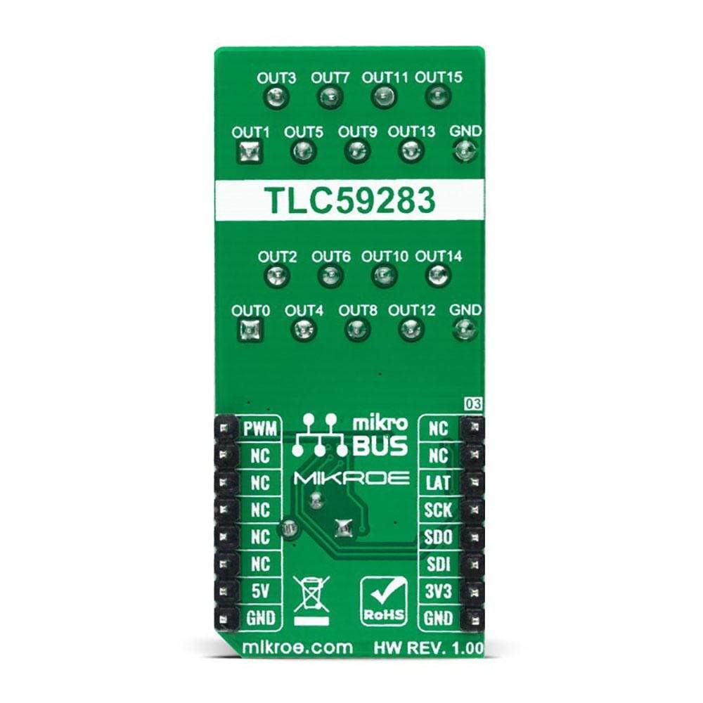
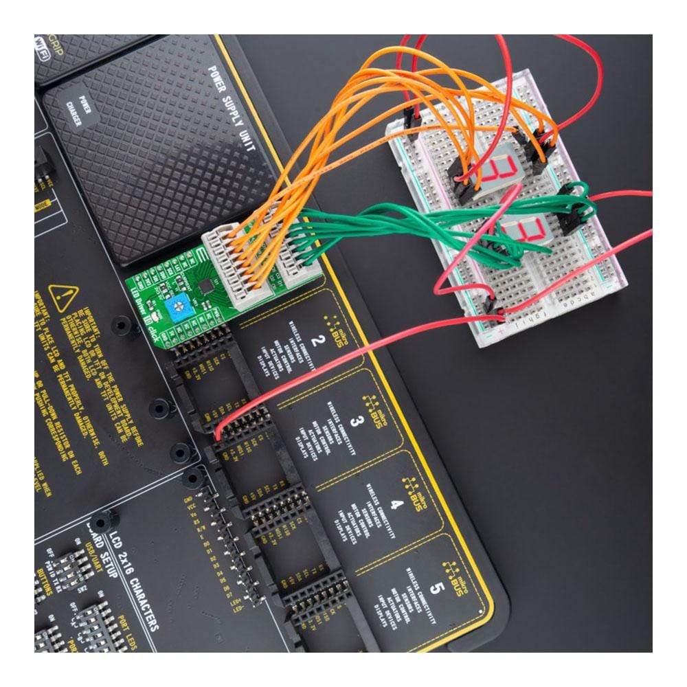
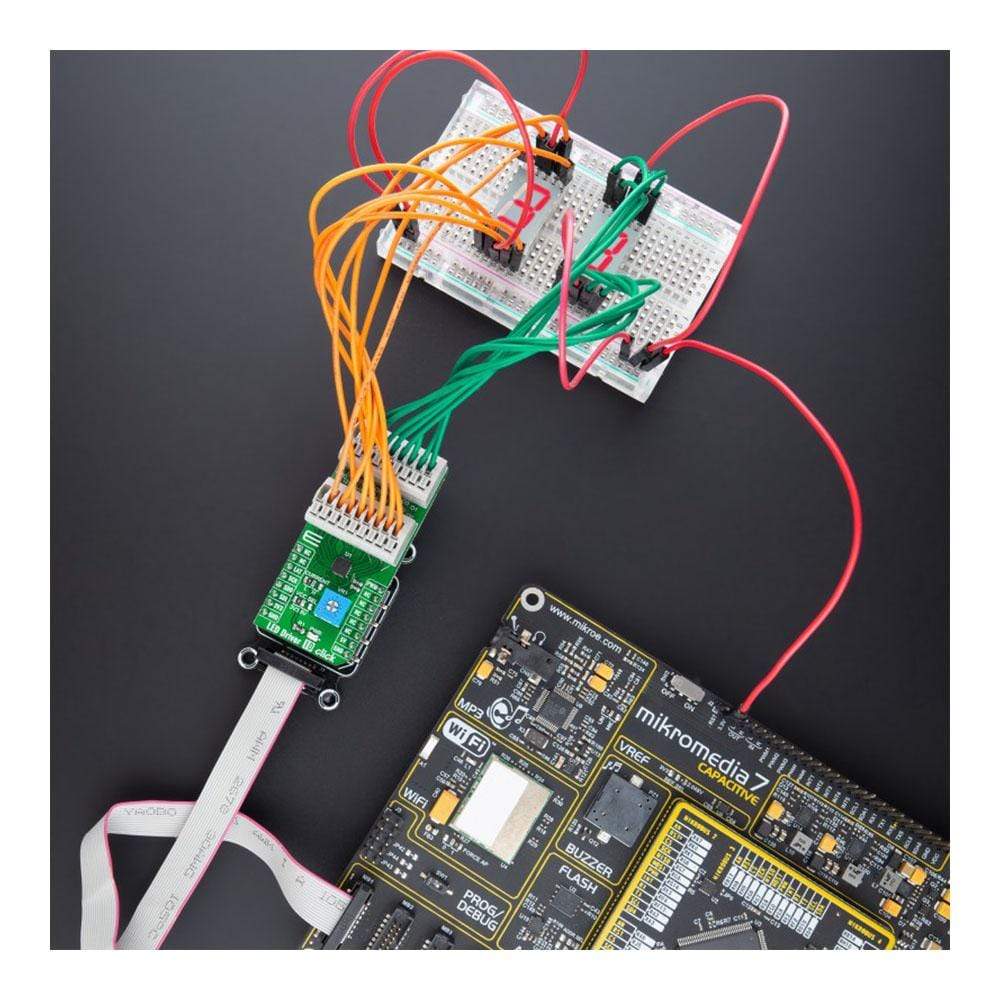
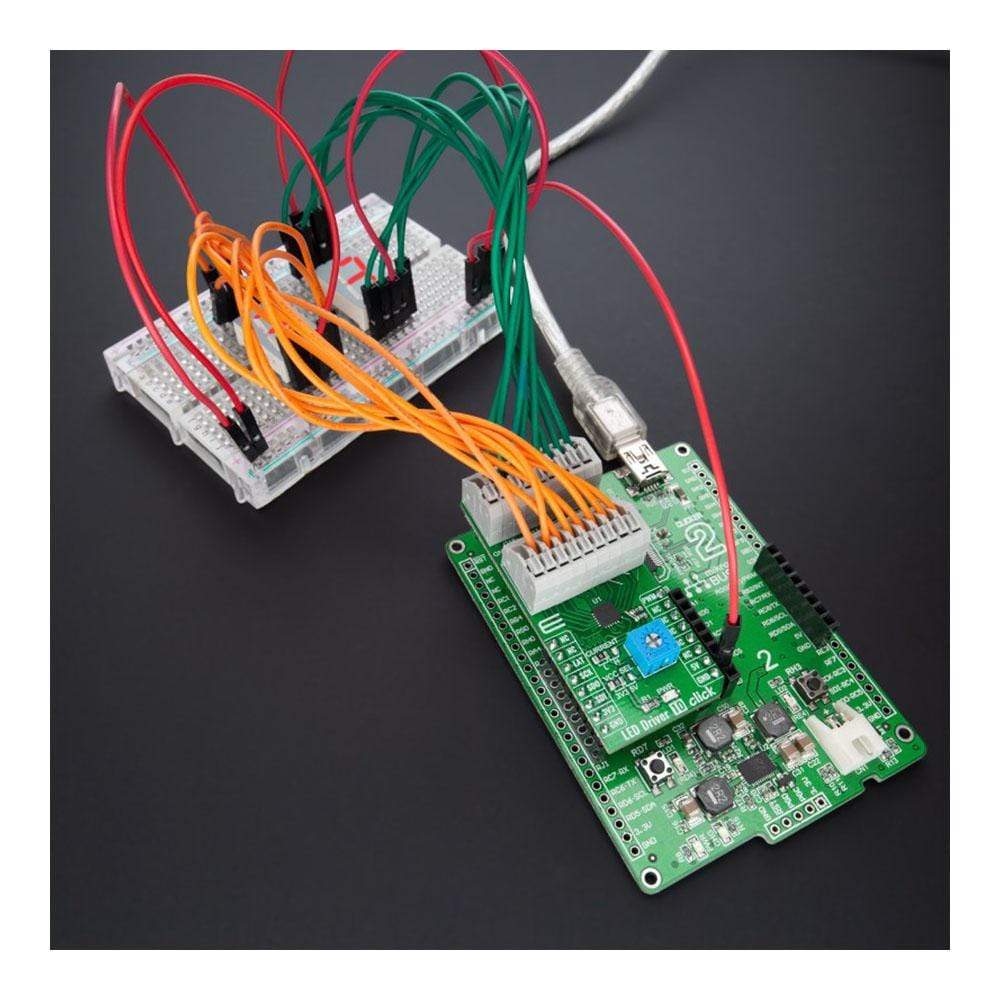
The LED Driver 10 Click Board™ is a compact add-on board that simplifies the control of multiple LEDs. This board features the TLC59283, a 16-channel, constant-current sink light-emitting diode (LED) driver with pre-charge FET from Texas Instruments. Each LED channel can be individually controlled with a simple SPI serial communication protocol compatible with both 3.3V or 5V logic levels. Each constant-current output has a pre-charge field-effect transistor that can reduce ghosting on the multiplexing drive LED display. It has additional features such as switching off all outputs via just one mikroBUS™ pin and setting the constant-current values on all 16 channels via one onboard potentiometer.
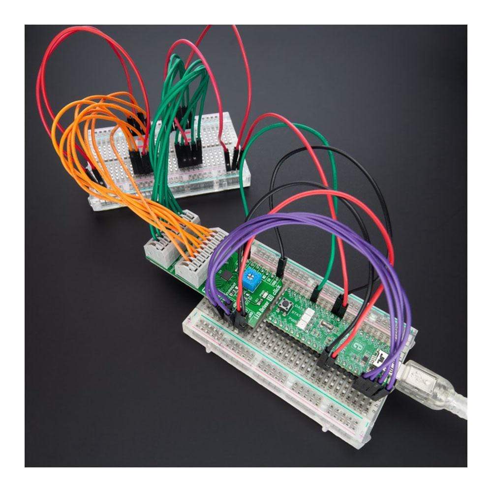
This LED Driver 10 Click Board™ is suitable for colour mixing and backlight application for amusement products, LED status signalization, home automation projects, and many more.
Downloads
Le Carte de pilote LED 10 Click Board™ est une carte complémentaire compacte qui simplifie le contrôle de plusieurs LED. Cette carte comprend le TLC59283, un pilote de diode électroluminescente (LED) à courant constant à 16 canaux avec FET de précharge de Texas Instruments. Chaque canal LED peut être contrôlé individuellement avec un simple protocole de communication série SPI compatible avec les niveaux logiques 3,3 V ou 5 V. Chaque sortie à courant constant dispose d'un transistor à effet de champ de précharge qui peut réduire les images fantômes sur l'affichage LED du lecteur de multiplexage. Il dispose de fonctionnalités supplémentaires telles que la désactivation de toutes les sorties via une seule broche mikroBUS™ et le réglage des valeurs de courant constant sur les 16 canaux via un potentiomètre intégré.
Ce LED Driver 10 Click Board™ convient au mélange de couleurs et aux applications de rétroéclairage pour les produits de divertissement, la signalisation d'état des LED, les projets de domotique et bien d'autres.
| General Information | |
|---|---|
Part Number (SKU) |
MIKROE-4787
|
Manufacturer |
|
| Physical and Mechanical | |
Weight |
0.02 kg
|
| Other | |
EAN |
8606027383403
|
Frequently Asked Questions
Have a Question?
Be the first to ask a question about this.