


Mikroelektronika d.o.o.
Mini-tableau à clic LCD
Mini-tableau à clic LCD
Impossible de charger la disponibilité du service de retrait
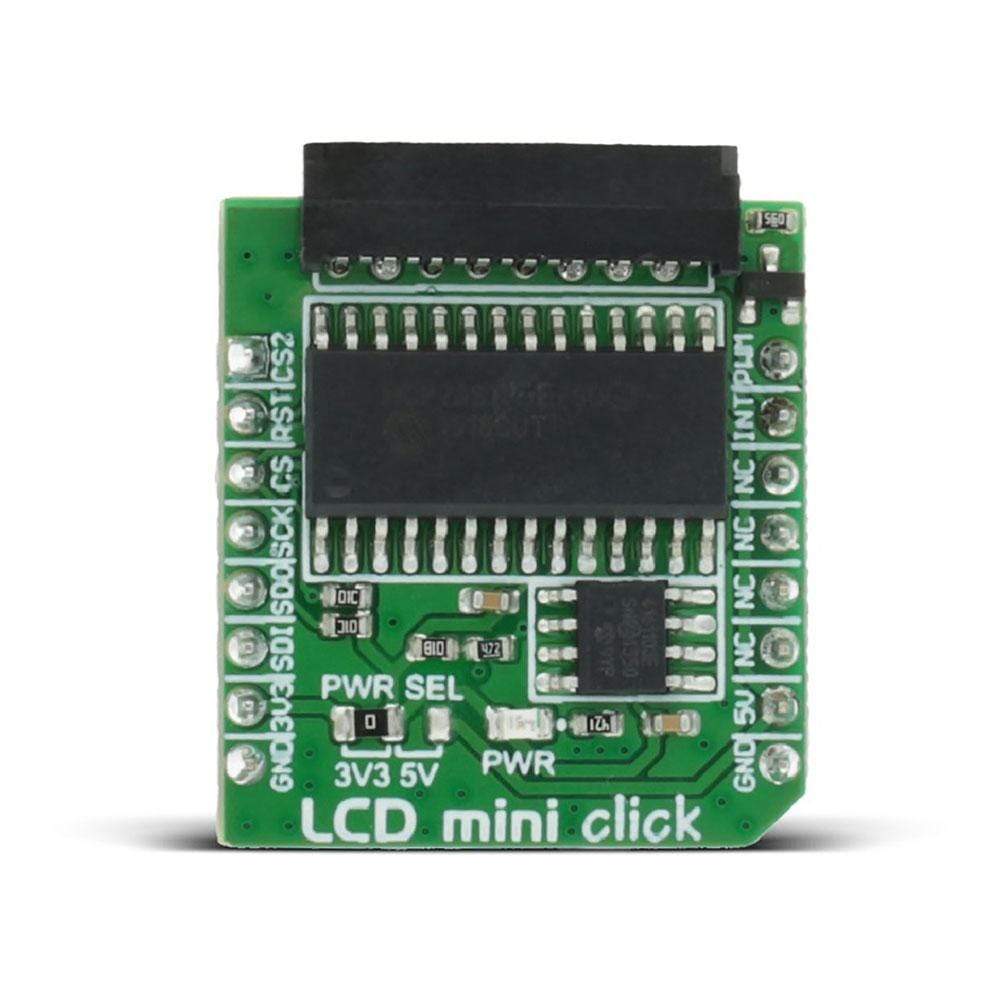
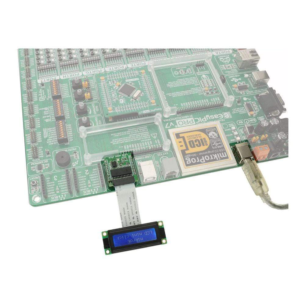
Le LCD Mini Click Board™ affiche 2x16 caractères monochromes sur un écran LCD LMB162XFW. Il est équipé de l'extenseur de port MCP23S17 et du potentiomètre numérique MCP4161, tous deux de Microchip.
Le mini Click Board™ LCD est conçu pour fonctionner sur une alimentation 3,3 V ou 5 V. Il communique avec le microcontrôleur cible via l'interface SPI et les broches suivantes sur la ligne MikroBUS : PWM, INT, RST, AN.
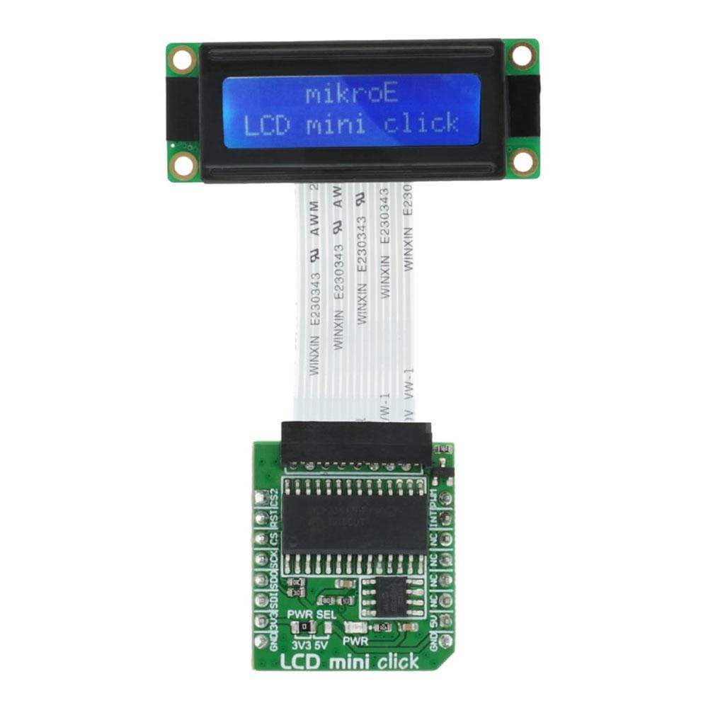


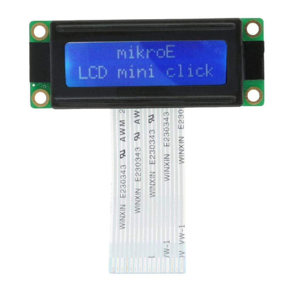

The LCD Mini Click Board™ displays 2x16 monochrome characters on an LMB162XFW LCD display. It features the MCP23S17 port expander and the MCP4161 digital potentiometer, both from Microchip. LCD mini click is designed to communicate with both 3.3V or 5V capable MCUs. The logic voltage level selection is done by the PWR SEL onboard SMD jumper. The 5V rail from the mikroBUS™ is used directly for powering up the included LCD screen. The click board™ communicates with the target microcontroller over the SPI interface and the following pins on the mikroBUS™ line: PWM, INT, RST, AN.
LCD AND BACKLIGHT CONTROL
The PWM pin onboard the LCD Mini Click Board™ is used for backlight control. While the digital potentiometer is used for contrast adjustments.
2X16 LCD DISPLAY FEATURES
2x16 LDC displays are ideal for displaying short messages and numbers. They can display 16 characters per one line, 32 in total. The 5x8 dot font displays characters, symbols, and numbers clearly and vividly.
SPECIFICATIONS
| Type | Adapter,LCD |
| Applications | Interfacing 2x16 LED displays with mikroBUS™ compatible development boards |
| On-board modules | MCP23S17 port expander, MCP4161 digital potentiometer - both from Microchip |
| Key Features | Adapter for connecting 2x16 LCD displays, MCP23S17 port expander, MCP4161 digital potentiometer |
| Interface | GPIO,PWM,SPI |
| Compatibility | mikroBUS |
| Click board size | S (28.6 x 25.4 mm) |
| Input Voltage | 3.3V or 5V |
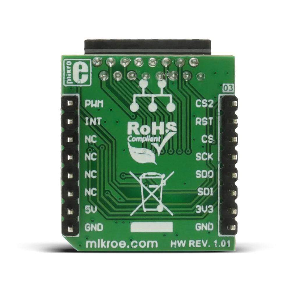
PINOUT DIAGRAM
This table shows how the pinout on the LCD Mini Click Board™ corresponds to the pinout on the mikroBUS™ socket (the latter shown in the two middle columns).
| Notes | Pin | Pin | Notes | ||||
|---|---|---|---|---|---|---|---|
| Digipot CS | CS2 | 1 | AN | PWM | 16 | PWM | Pulse-Width Modulation |
| Reset for the port expander | RST | 2 | RST | INT | 15 | INT | INT from the port expander |
| SPI chip select | CS | 3 | CS | RX | 14 | NC | |
| SPI clock | SCK | 4 | SCK | TX | 13 | NC | |
| SPI Master Input Slave Output | MISO | 5 | MISO | SDA | 12 | NC | |
| SPI Master Output Slave Input | MOSI | 6 | MOSI | SDA | 11 | NC | |
| Power supply | +3.3V | 7 | 3.3V | 5V | 10 | +5V | Power supply |
| Ground | GND | 8 | GND | GND | 9 | GND | Ground |
Software Support
The demo shows how to use the SPI LCD library to communicate with the LCD (with HD44780 compliant controllers) in 4-bit mode via the SPI interface. It also uses the PWM for the backlight and the on board digital potentiometer, for controlling display contrast, which can be accessed through SPI. The demo iterates through all the values for the backlight and the contrast intensity.
CODE SNIPPET
The main function of the demo.
01 void main()
02 {
03     system_init();
04
05     SPI_Lcd_Out(1, 6, "mikroE");
06     SPI_Lcd_Out(2, 2, "LCD mini click");
07
08     set_bcklight(0xFF);
09     set_contrast(0xDF);
10
11     Delay_ms(5000);
12
13     while (1)
14     {
15         set_bcklight(value);
16         set_contrast(value);
17
18         value++;
19         delay_ms(40);
20     }
21 }
Mini-tableau à clic LCD
Frequently Asked Questions
Have a Question?
Be the first to ask a question about this.