Tableau de clic Force 5
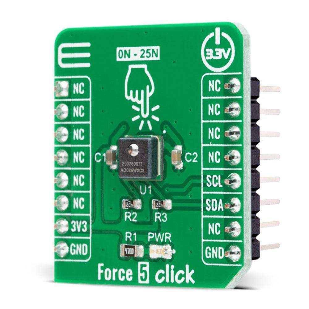
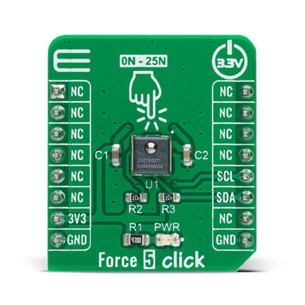
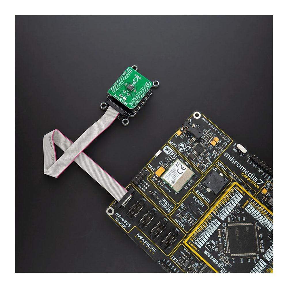
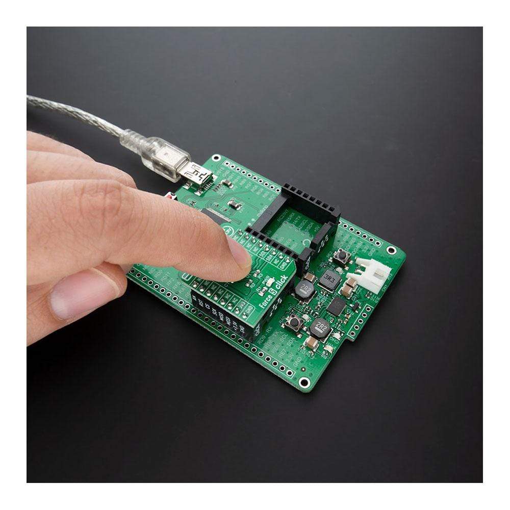
Le Force 5 Click Board™ est une carte complémentaire compacte qui contient un micro capteur de force compensé/amplifié stable et flexible. Cette carte comprend le FMAMSDXX025WC2C3, un capteur de force piézorésistif offrant une sortie numérique pour la lecture de la force sur la plage de force à pleine échelle spécifiée et une plage de température de Honeywell Sensing and Productivity Solutions. La sortie numérique très stable qui est directement proportionnelle à la force appliquée à la sphère couplée mécaniquement, la précision améliorée et la bande d'erreur totale réduite qui améliore les performances du système ne sont que quelques-unes des bonnes caractéristiques de ce capteur. Ce Click Board™ convient aux applications industrielles telles que les équipements de mesure de force/adhérence, la détection de charge et de compression, la robotique, etc.
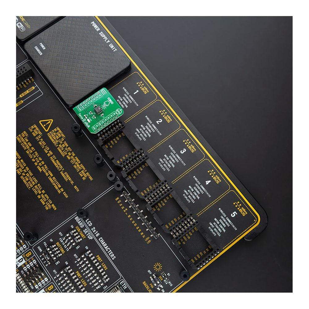
Force 5 Click est pris en charge par une bibliothèque compatible mikroSDK, qui comprend des fonctions qui simplifient le développement logiciel. Cette Click Board™ est un produit entièrement testé, prêt à être utilisé sur un système équipé du socket mikroBUS™.
How Does The Force 5 Click Board™ Work?
The Force 5 Click Board™ is based on the FMAMSDXX025WC2C3, a piezoresistive-based force sensor offering a digital output for reading force over the specified full-scale force span and a temperature range from Honeywell Sensing and Productivity Solutions. This sensor belongs to the group the FMA Series designed to meet the user's need for a compensated, amplified force sensor that provides digital outputs, a variety of force sensing ranges, a small, cost-effective format, and enhanced durability and accuracy.
The flexible design of the FMAMSDXX025WC2C3 operates over a wide operating temperature range. It has a force range of 25 newtons that maximizes sensitivity and improve system resolution/performance, enhanced accuracy which includes all errors due to force non-linearity and non-repeatability, and diagnostic functions which allow the user to determine if the sensor is working correctly by detecting if electrical paths are broken or shorted inside the sensor. This Click board™ offers a very stable digital output that is directly proportional to the force applied to the mechanically-coupled sphere that enhances performance through reduced conversion requirements and the convenience of a direct interface to MCU.
The Force 5 Click Board™ communicates with MCU using the standard I2C 2-Wire interface with a maximum frequency of 400kHz. This Click board™ is easy to program because it does not require an overly demanding configuration. The code example that MikroE provides to its users consists of calibrating the sensor and displaying the diagnostic status (whether the sensor is in Normal operation, Command mode, or Stale mode). After successful calibration, the force and temperature are measured, after which the digital output data are displayed every 500 ms.
This Click board™ is designed to be operated only with a 3.3V logic voltage level. A proper logic voltage level conversion should be performed before the Click board™ is used with MCUs with different logic levels. However, the Click board™ comes equipped with a library that contains easy to use functions and an example code that can be used as a reference for further development.
Specifications
Type | Force |
Applications | Can be used for industrial applications such as force/grip measuring equipment, load and compression sensing, robotics, and more. |
On-board modules | The Force 5 Click Board™ is based on the FMAMSDXX025WC2C3, a piezoresistive-based force sensor offering a digital output for reading force over the specified full-scale force span and a temperature range from Honeywell Sensing and Productivity Solutions. |
Key Features | Low power consumption, stable digital output, enhanced durability and accuracy, reduced total error band, and more. |
Interface | I2C |
Compatibility | mikroBUS |
Click board size | S (28.6 x 25.4 mm) |
Input Voltage | 3.3V |
Pinout diagram
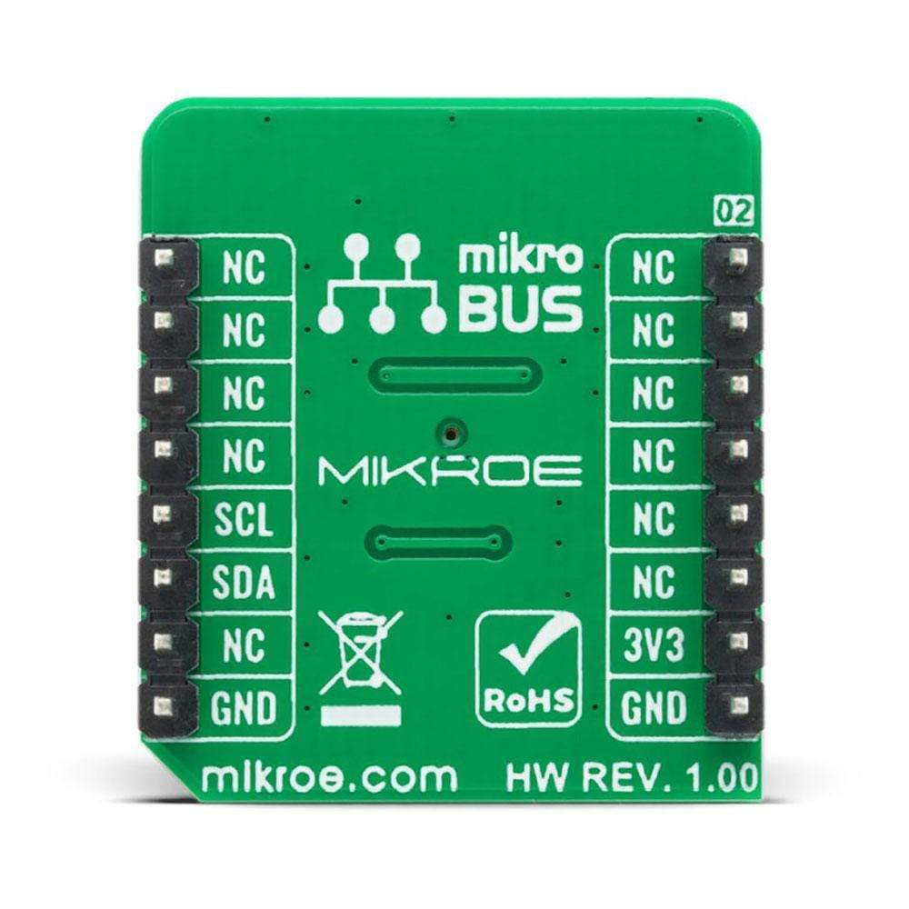
This table shows how the pinout on the Force 5 Click Board™ corresponds to the pinout on the mikroBUS™ socket (the latter shown in the two middle columns).
Notes | Pin | Pin | Notes | ||||
---|---|---|---|---|---|---|---|
NC | 1 | AN | PWM | 16 | NC | ||
NC | 2 | RST | INT | 15 | NC | ||
NC | 3 | CS | RX | 14 | NC | ||
NC | 4 | SCK | TX | 13 | NC | ||
NC | 5 | MISO | SCL | 12 | SCL | I2C Clock | |
NC | 6 | MOSI | SDA | 11 | SDA | I2C Data | |
Power Supply | 3.3V | 7 | 3.3V | 5V | 10 | NC | |
Ground | GND | 8 | GND | GND | 9 | GND | Ground |
Onboard settings and indicators
Label | Name | Default | Description |
---|---|---|---|
LD1 | PWR | - | Power LED Indicator |
Force 5 Click electrical specifications
Description | Min | Typ | Max | Unit |
---|---|---|---|---|
Supply Voltage | 3 | 3.3 | 3.6 | V |
Force Range | 0 | - | 2.5 | N |
Output Resolution | 12 | - | - | bits |
Accuracy | - | ±2 | - | %FSS |
Operating Temperature Range | -40 | - | +85 | °C |
Software Support
We provide a library for the Force 5 Click Board™ on our LibStock page, as well as a demo application (example), developed using MikroElektronika compilers. The demo can run on all the main MikroElektronika development boards.
Library Description
The library covers all the necessary functions to control the Force 5 Click Board™. The library performs a standard I2C interface communication.
Key Functions
void force5_read_all_data ( force5_data_t *force_data )
- Read all data function.float force5_get_force ( force5_calibration_t calib_data )
- Get force function.float force5_get_temperature ( void )
- Get temperature function.
Example Description
The application is composed of three sections :
- The application is composed of three sections :
- Application Initialization - Initialization driver enables - I2C, calibration the device, display diagnostic states and temperature.
- Application Task - (code snippet) This is an example that demonstrates the use of the Force 5 Click Board™. Force 5 Click board can be used to measure digital output force ( N ). All data logs write on USB uart changes every 500 milliseconds.
void application_task ( ) { force_n = force5_get_force( calib_data ); FloatToStr( force_n, log_text ); mikrobus_logWrite( " Force : ", _LOG_TEXT ); mikrobus_logWrite( log_text, _LOG_TEXT ); mikrobus_logWrite( " N", _LOG_LINE ); mikrobus_logWrite( "-------------------------", _LOG_LINE ); Delay_ms( 500 ); }
The full application code, and ready to use projects can be found on our LibStock page.
Other mikroE Libraries used in the example:
- I2C
- UART
- Conversions
Additional Notes and Information
Depending on the development board you are using, you may need a USB UART click, USB UART 2 click or RS232 click to connect to your PC, for development systems with no UART to USB interface available on the board. The terminal available in all MikroElektronika compilers, or any other terminal application of your choice, can be used to read the message.
mikroSDK
The Force 5 Click Board™ is supported with mikroSDK - MikroElektronika Software Development Kit. To ensure proper operation of mikroSDK compliant Click board™ demo applications, mikroSDK should be downloaded from the LibStock and installed for the compiler you are using.
Tableau de clic Force 5
Frequently Asked Questions
Have a Question?
Be the first to ask a question about this.