Carte à clic Fan 2
Carte à clic Fan 2
Overview
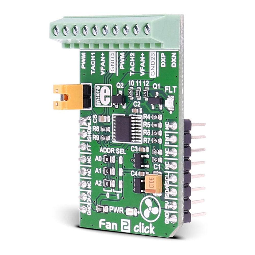
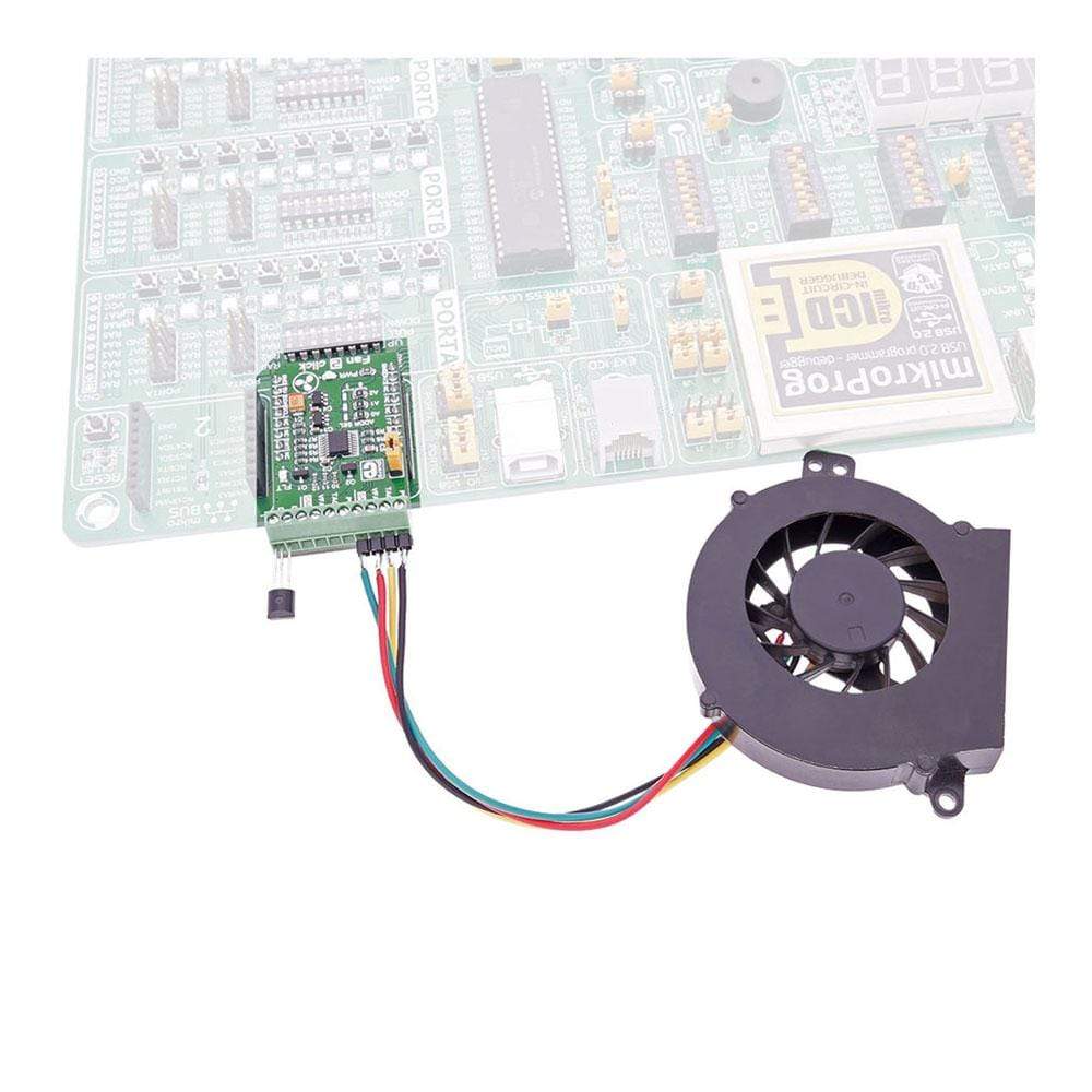
Le Fan 2 Click Board™ est équipé du contrôleur de vitesse de ventilateur de précision MAX31760. Il peut mesurer la température et ajuster la vitesse du ventilateur pour maintenir la température au même niveau. Le Fan 2 Click Board™ peut également contrôler deux ventilateurs en même temps.
Le Fan 2 Click Board™ est conçu pour fonctionner sur une alimentation 3,3 V ou 5 V. Il communique avec le microcontrôleur cible via l'interface I2C, avec des fonctionnalités supplémentaires fournies par les broches suivantes sur la ligne MikroBUS : INT, AN, RST, CS.
The Fan 2 Click Board™ carries the MAX31760 precision fan-speed controller. It can measure temperature and adjust the fan speed to keep the temperature at the same level. Fan 2 click can also control two fans at the same time.
The Fan 2 Click Board™ is designed to run on either 3.3V or 5V power supply. It communicates with the target microcontroller over I2C interface, with additional functionality provided by the following pins on the mikroBUS™ line: INT, AN, RST, CS.
For example, you can set the limit at 25°C and if the temperature goes over that the click will activate the fan; it will keep working until the temperature is 25°C again.
MAX31760 CONTROLLER FEATURES
The MAX31760 integrates temperature sensing along with precision PWM fan control. It accurately measures its local die temperature and the remote temperature of a discrete diode-connected transistor, such as a 2N3906, or a thermal diode commonly found on CPUs, graphics processor units (GPUs), and other ASICs. Multiple temperature thresholds, such as local high/overtemperature (OT) and remote high/overtemperature, can be set by an I 2 C-compatible interface.
Fan speed is controlled based on the temperature reading as an index to a 48-byte lookup table (LUT) containing user-programmed PWM values. The flexible LUT-based architecture enables the user to program a smooth nonlinear fan speed vs. temperature transfer function to minimize acoustic fan noise. Two tachometer inputs allow measuring the speeds of two fans independently.
See the datasheet for more information.
How Does The Fan 2 Click Board™ Work?
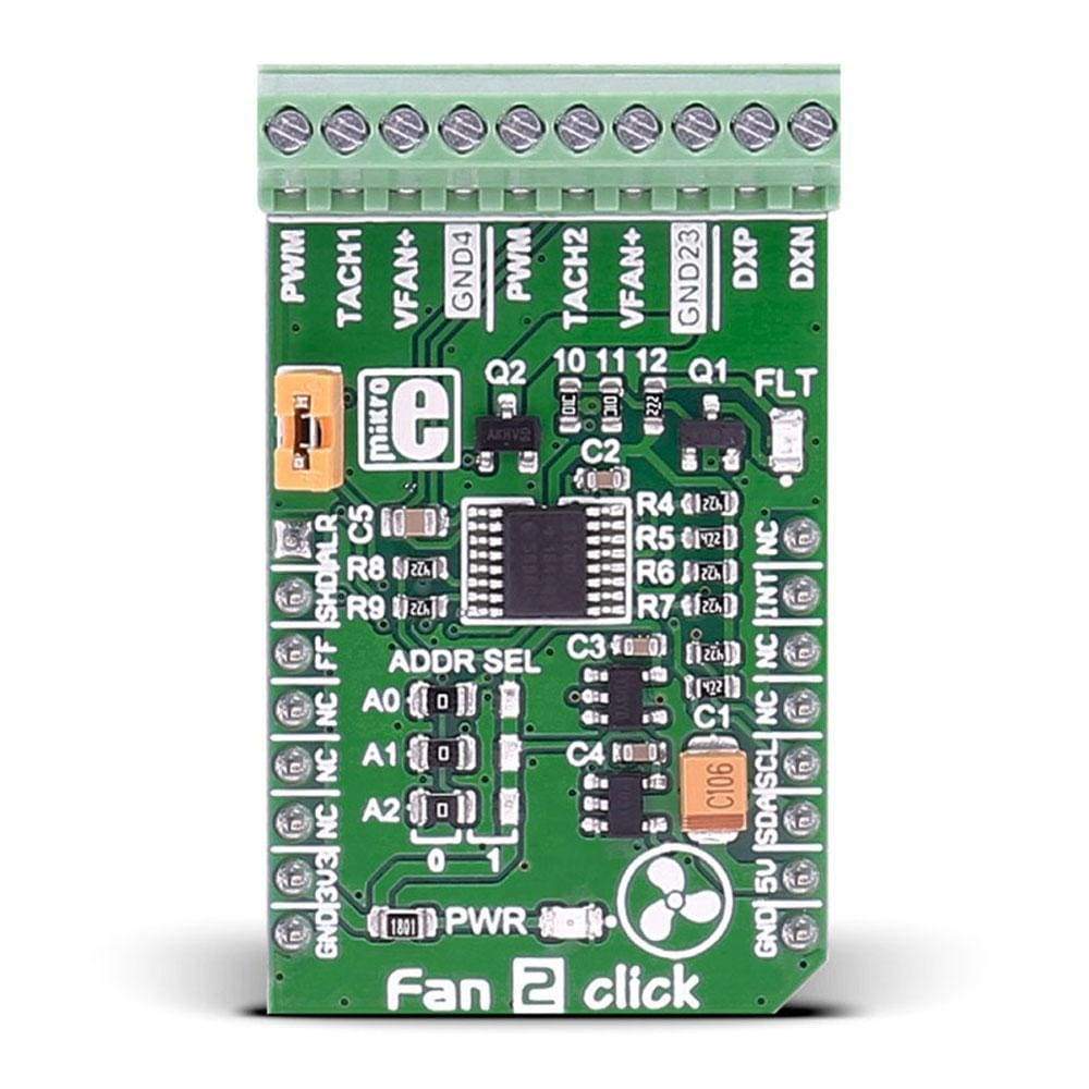
The Fan 2 Click Board™ carries a 10-pole terminal block, that allows easy connection for pairs of two, three or four wire DC fans, on the standard way of connection via PWM, TACH, GND, VFAN lines.
A single onboard jumper setting enables 2 or 3 wire fan connection. In addition, there are two points (DXP, DXN) on the same terminal for external temperature sensor connection. The Fan 2 Click Board™ communicates with the MCU over data interface voltage level of 3.3V only.
SPECIFICATIONS
Type | Brushless |
Applications | For speed control of DC fans (5/12 VDC) than could be found on PCs, servers, network equipment, set-top-box and digital-video-recorder devices, and many other consumer electronics, or storage containers like RAID systems etc. |
On-board modules | MAX31760 precision fan-speed controller |
Key Features | measure temperature and adjust the fan speed to keep the temperature at the same level |
Interface | I2C |
Compatibility | mikroBUS |
Click board size | M (42.9 x 25.4 mm) |
Input Voltage | 3.3V,5V |
PINOUT DIAGRAM
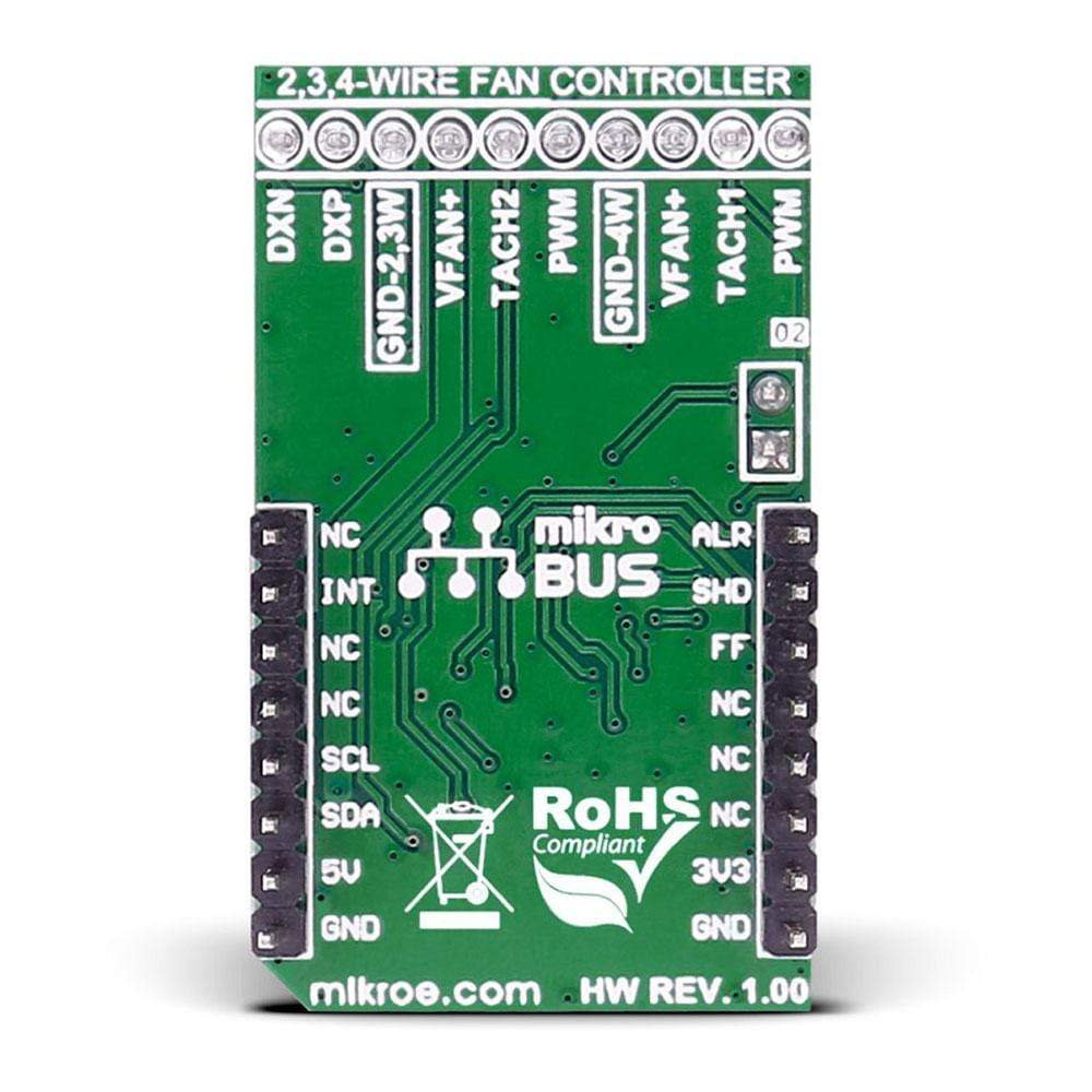
This table shows how the pinout on the Fan 2 Click Board™ corresponds to the pinout on the mikroBUS™ socket (the latter shown in the two middle columns).
Notes | Pin | Pin | Notes | ||||
---|---|---|---|---|---|---|---|
#ALERT, active low, local/remote overtemperature fault | ALR | 1 | AN | PWM | 16 | NC | |
#SHDN, active low overtemperature shutdown fault | SHD | 2 | RST | INT | 15 | INT | #INT, active low, at least one of the three faults has occurred |
#FANFAULT, active low, fan speed fault | FF | 3 | CS | TX | 14 | NC | |
NC | 4 | SCK | RX | 13 | NC | ||
NC | 5 | MISO | SCL | 12 | SCL | SCL I2C line | |
NC | 6 | MOSI | SDA | 11 | SDA | SDA I2C line | |
Power supply | +3.3V | 7 | 3.3V | 5V | 10 | +5V | Power supply |
Ground | GND | 8 | GND | GND | 9 | GND | Ground |
JUMPERS AND SETTINGS
Designator | Name | Default Position | Default Option | Description |
---|---|---|---|---|
J1 | FAN SEL | ON or OFF (not specified) | 2/3 or 4 wire fan | When in place (ON position) it enables two or three wire fan usage, in otherwise (OFF - unconnected) it enables 4-wire fan applications. |
Software Support
Code examples for the Fan 2 Click Board™, written for MikroElektronika hardware and compilers are available on Libstock.
CODE SNIPPET
The following code snippet shows 3 functions from the example that control the fan speed. The first one initializes the Fan 2 Click Board™ to work automatically, depending on the temperature, while the second and third one demonstrates manual control.
01 //sets fan to automatic control (default), and fills the look-up table 02 void Fan_2_Init() 03 { 04 FAN2_I2CdriverInit( I2CM1_Set_Slave_Address, 0, 0, I2CM1_Write_Bytes, I2CM1_Read_Bytes); 05 FAN2_sendCommand(_FAN2_CONTROL_REGISTER_1, _FAN2_CMD1_DEFAULT); 06 FAN2_sendCommand(_FAN2_CONTROL_REGISTER_2, _FAN2_CMD2_DEFAULT); 07 FAN2_sendCommand(_FAN2_CONTROL_REGISTER_3, _FAN2_CMD3_DEFAULT | _FAN2_CMD3_INSTANT_RAMP); 08 FAN2_setupLUT(LUTSettings); 09 } 10 11 //sets fan to manual control 12 void Fan_2_Manual() 13 { 14 FAN2_sendCommand(_FAN2_CONTROL_REGISTER_1, _FAN2_CMD1_DEFAULT); 15 FAN2_sendCommand(_FAN2_CONTROL_REGISTER_2, _FAN2_CMD2_DEFAULT | _FAN2_CMD2_DIRECT_CONTROL); 16 FAN2_sendCommand(_FAN2_CONTROL_REGISTER_3, _FAN2_CMD3_DEFAULT | _FAN2_CMD3_INSTANT_RAMP); 17 } 18 19 //turns fan on and off 20 void Fan_2_Task() 21 { 22 FAN2_sendCommand(_FAN2_DIRECT_CONTROL_REGISTER, _FAN2_DUTYCYCLE_100); 23 delay_ms (5000); 24 FAN2_sendCommand(_FAN2_DIRECT_CONTROL_REGISTER, _FAN2_DUTYCYCLE_0); 25 delay_ms (5000); 26 }
Frequently Asked Questions
Have a Question?
Be the first to ask a question about this.