

Mikroelektronika d.o.o.
Planche à clic Buck-Boost 3
Planche à clic Buck-Boost 3
SKU: MIKROE-3277
Impossible de charger la disponibilité du service de retrait


Overview
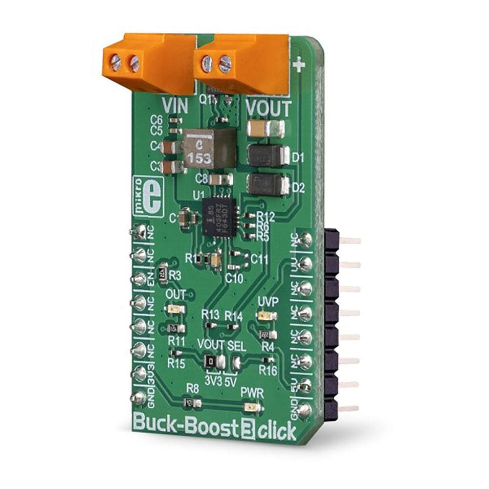
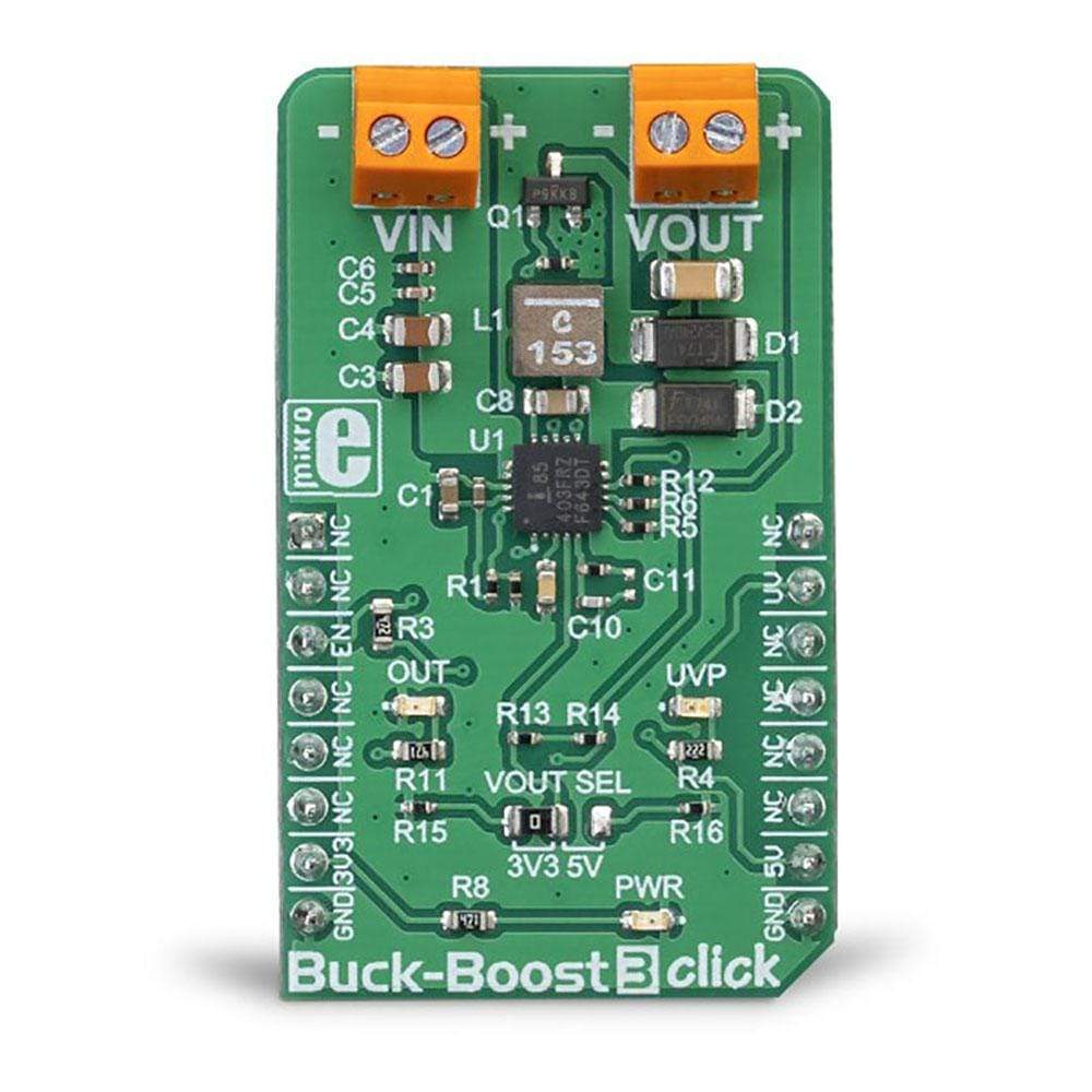
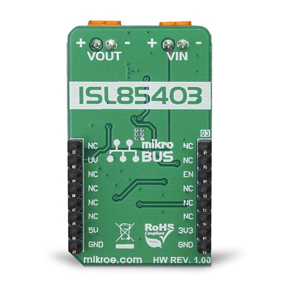
The Buck-Boost 3 Click Board™ is a voltage converter/regulator, which is able to provide a regulated voltage of 3.3V or 5V on the output, even when the input voltage drops under 3V. This is possible thanks to the ISL85403, a specialised buck-boost voltage converter IC which features an integrated high-side MOSFET and a low-side driver, that can be used to drive an external MOSFET.
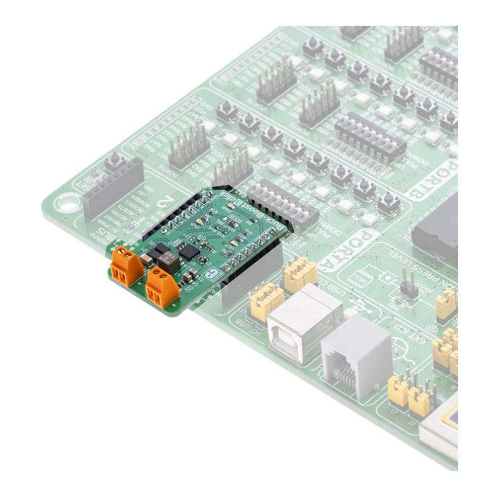
Buck-Boost 3 Click Board™ perfectly suited to provide power with regulated voltage for embedded applications, points of load, or to be used as the battery voltage regulator, or in similar general-purpose power applications that require regulated 3.3V or 5V power supply.
Downloads
Le Buck-Boost 3 Click Board™ est un convertisseur/régulateur de tension capable de fournir une tension régulée de 3,3 V ou 5 V en sortie, même lorsque la tension d'entrée chute en dessous de 3 V. Ceci est possible grâce à l'ISL85403, un circuit intégré de convertisseur de tension buck-boost spécialisé qui dispose d'un MOSFET côté haut intégré et d'un pilote côté bas, qui peut être utilisé pour piloter un MOSFET externe.
Buck-Boost 3 Click Board™ parfaitement adapté pour fournir une alimentation avec une tension régulée pour les applications embarquées, les points de charge, ou pour être utilisé comme régulateur de tension de batterie, ou dans des applications d'alimentation à usage général similaires qui nécessitent une alimentation régulée de 3,3 V ou 5 V.
| General Information | |
|---|---|
Part Number (SKU) |
MIKROE-3277
|
Manufacturer |
|
| Physical and Mechanical | |
Weight |
0.02 kg
|
| Other | |
EAN |
8606018714056
|
Frequently Asked Questions
Have a Question?
Be the first to ask a question about this.