Carte Brushless 5 Click
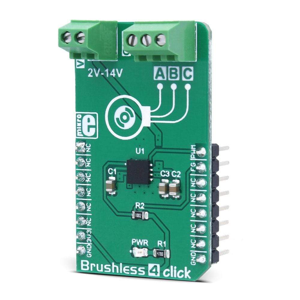
Le Brushless 5 Click Board™ est un contrôleur de moteur BLDC triphasé sans capteur, doté d'une fonction de commutation douce pour réduire le bruit du moteur et les EMI, et d'une détection précise du moteur BEMF, ce qui élimine le besoin de capteurs à effet Hall dans les applications de moteur. Il peut piloter des moteurs 5 V-16 V avec un courant allant jusqu'à 500 mA. Le pilote de moteur permet le contrôle de la vitesse via le signal PWM du microcontrôleur hôte. Il dispose également d'une broche de sortie pour lire la vitesse du moteur. La commutation de phase retardée assure un démarrage fiable du moteur, tandis que la fonction de détection de verrouillage empêche les dommages et la surchauffe.
The Brushless 5 Click Board™ is a 3 phase sensorless BLDC motor controller, with a soft-switching feature for reduced motor noise and EMI, and precise BEMF motor sensing, which eliminates the need for Hall-sensors in motor applications. It can drive 5V-16V motors with up to 500 mA current. The motor driver allows speed control via the PWM signal from the host MCU. It also features an output pin for reading the speed of the motor. Delayed phase commutation ensures a reliable motor start, while the Lock Detect function prevents damage and overheating.
The driver IC requires a low count of external components, due to its high degree of integration. Three half-bridge NMOS power outputs are integrated on the IC die and are used to drive the coils of the BLDC motor. Considering all the driving and protection features it has, Brushless 5 click an ideal solution for developing cost-effective and reliable BLDC motor driving applications, such as the computer fan coolers, power supply fans, small BLDC motor applications and similar.
How Does The Brushless 5 Click Board™ Work?
The Brushless 5 Click Board™ uses the A4941, a three-phase sensorless fan driver IC, made by Allegro MicroSystems LLC. This IC features a proprietary sensorless BEMF zero-crossing sensing technique, which provides a speed reading via the FG output pin, routed to the INT pin of the mikroBUS™. The BEMF zero-crossing is the point where the voltage of the undriven motor winding (BEMF is short for Back Electromotive Force) crosses the motor center tap (neutral point) voltage. Neutral point voltage can be approximated using an internally generated reference voltage, in the case when the used motor does not provide one. BEMF zero-crossing occurs when a pole of the rotor is in alignment with a pole of the stator and is used as a positional reference for the commutation controller section of the A4941 IC.
When the zero-crossing occurs, an internal signal is set to a HIGH state, while the beginning of the next phase commutation sets this signal to a LOW state. The signal is latched between the states so that commutation transients do not affect it. This provides a robust and accurate position sensing system.
The internal sequencer is used to commutate the phases, based on the position feedback. During the startup period, the phase commutation is provided by the internal oscillator instead, until a valid BEMF positional signal sequence is detected. The current through the coils is maximum at this stage since the PWM signal with 100% duty cycle is applied during a start-up sequence.
As already mentioned, the motor speed can be calculated using the FG output pin. The final calculation will depend on the FG frequency, as well as the number of the motor poles and slots. To calculate the actual RPM of the motor, the following formula should be applied:
Where:
PP = Number of magnetic pole pairs of the rotor
FG = Output signal frequency at the FG pin
The Lock Detect feature prevents the motor lock up or fall out of synchronization while protecting the coils and the IC of overheating. If a valid FG signal is not detected for 2 seconds, the outputs are disabled for 5 seconds. After this time-out, another restart is attempted.
An internal peak overcurrent protection is set to about 1A. If the motor drains more than 1A, especially during the startup, the overcurrent protection will be activated, disabling the output stage for about 25µs. This can prevent the startup of some types of motors and for this reason, the longest startup delay of 200ms is chosen for the Brushless 5 Click Board™.
The PWM pin is routed to the same pin of the mikroBUS™, and it can be used to control the current through the coils. When the HIGH logic level is applied to the PWM input pin, the current from the power supply flows through the coils. When the LOW logic level is applied to the PWM input pin, there is no current running through the coils. Applying PWM signal with a frequency of 15 kHz to 30 kHz will result in a coil current that corresponds to the duty cycle of the applied PWM. A minimum pulse width is fixed at 6 μs, allowing the minimum speed to be maintained, even when applying PWM signals with very low duty cycle. Applying a LOW logic level to the PWM pin for more than 500µs will put the device into the low power consumption (standby) mode.
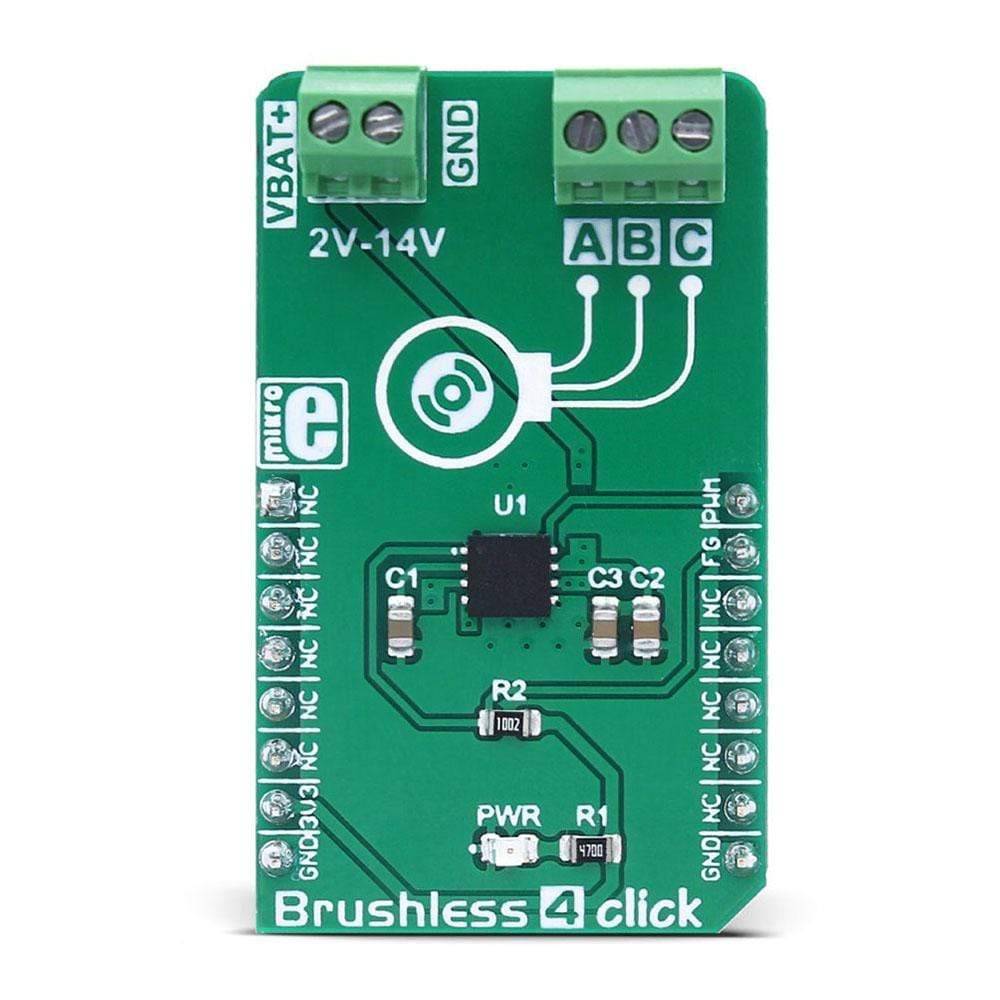
The power supply for the motor coils is connected via the external two-pole terminal. VBAT+ input is connected to the positive voltage, while the GND input is connected to the ground of the power supply. The voltage of the external power supply should stay between 5V and 16V. The most common use is with 12V motors.
The BLDC motor coils should be connected to the four-pole output screw terminal. Respective motor phases are connected to the A, B, and C terminal outputs, while the central point of the BLDC motor can be connected to the output labeled as N. IF the used BLDC motor does not have the central (neutral) point output, the neutral point needed for the BEMF sensing will be generated internally.
SPECIFICATIONS
Type | Brushless |
Applications | The Brushless 5 Click Board™ is ideal for driving small 5V to 16V sensorless BLDC motor driving, silent computer cooling fan driving, efficient air ventilation systems, and similar applications that could benefit of having reliable and simple motor driver circuit |
On-board modules | A4941, a three-phase sensorless fan driver, from Allegro MicroSystems LLC |
Key Features | Overcurrent limiting, thermal protection, rotor lock protection, sensorless operation, low count of additional components required, soft-switching function, edge terminals for an easy connection |
Interface | PWM |
Compatibility | mikroBUS |
Click board size | M (42.9 x 25.4 mm) |
Input Voltage | 3.3V |
PINOUT DIAGRAM
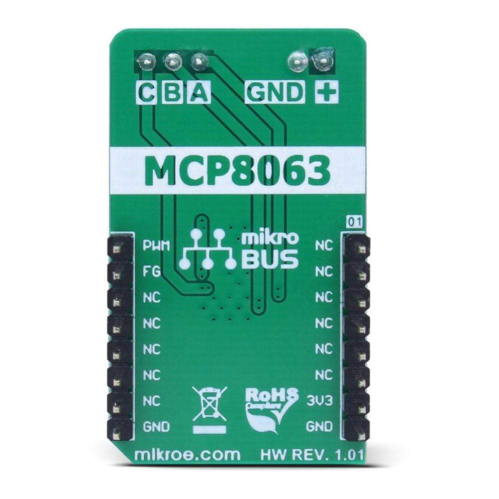
This table shows how the pinout on the Brushless 5 Click Board™ corresponds to the pinout on the mikroBUS™ socket (the latter shown in the two middle columns).
Notes | Pin | Pin | Notes | ||||
---|---|---|---|---|---|---|---|
NC | 1 | AN | PWM | 16 | PWM | PWM speed control IN | |
NC | 2 | RST | INT | 15 | FG | Motor speed indication OUT | |
NC | 3 | CS | RX | 14 | NC | ||
NC | 4 | SCK | TX | 13 | NC | ||
NC | 5 | MISO | SCL | 12 | NC | ||
NC | 6 | MOSI | SDA | 11 | NC | ||
Power supply | 3.3V | 7 | 3.3V | 5V | 10 | NC | |
Ground | GND | 8 | GND | GND | 9 | GND | Ground |
BRUSHLESS 5 CLICK ELECTRICAL SPECIFICATIONS
Description | Min | Typ | Max | Unit |
---|---|---|---|---|
Peak current limit | - | - | 1.1 | A |
Normal running current | - | - | 500 | mA |
Input power supply voltage | 5 | - | 16 | V |
Lock protection waiting time | 4.0 | 5.0 | 6.0 | s |
Thermal shutdown | 150 | 165 | 180 | ˚C |
ONBOARD SETTINGS AND INDICATORS
Label | Name | Default | Description |
---|---|---|---|
LD1 | PWR | - | Power LED indicator |
CON1 | VBAT | - | Power supply input terminal |
CON2,3 | A,B,C,N | - | BLDC motor connector |
Software Support
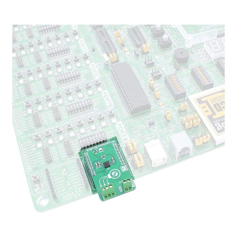
We provide a demo application for the Brushless 5 Click Board™ on our Libstock page, as well as a demo application (example), developed using MikroElektronika compilers. The demo can run on all the main MikroElektronika development boards.
Library Description
The library provides generic functions for working with the Brushless 5 Click Board™.
Key Functions
void brushless5_motorParameters(uint8_t poles, uint8_t slots)
- Sets the number of poles and slots of the motor. This needs to be set correctly for the calculation to be correctuint16_t brushless5_getSpeed(uint16_t pulseSample)
- Calculates the speed of accumulated pulses from the interrupt pin and returns the motor speed value.uint8_t brushless5_intGet()
- Returns the state of the interrupt pin.
Example Description
The application is composed of three sections:
- System Initialization - Initializes the GPIO structure.
- Application Initialization - Initializes the GPIO driver and configures the PWM
peripheral for controlling the speed of the motor. - Application Task - (code snippet) - Increases and decreases the speed of the motor demonstrating the speed control.
void applicationTask() { for(i=0;i<pwm_period;i++) { brushless5_setSpeed(i); Delay_ms(10); } Delay_ms(1000); for(i=pwm_period;i>1;i--) { brushless5_setSpeed(i); Delay_ms(10); } Delay_ms(1000); }
void brushless5_pwmInit()
- Initializations of the PWM on the mikroBUS 1.void brushless5_setSpeed(uint16_t speed)
- Sets the PWM signal for the motor.
The full application code, and ready to use projects can be found on our Libstock page.
Other MikroElektronika libraries used in the example:
- PWM Library
Additional Notes and Information
Depending on the development board you are using, you may need a USB UART click, USB UART 2 click or RS232 click to connect to your PC, for development systems with no UART to USB interface available on the board. The terminal available in all MikroElektronika compilers, or any other terminal application of your choice, can be used to read the message.
Carte Brushless 5 Click
Frequently Asked Questions
Have a Question?
Be the first to ask a question about this.