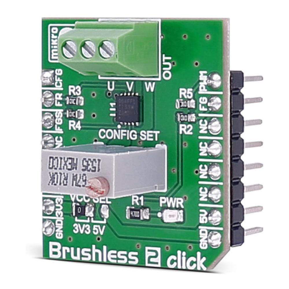
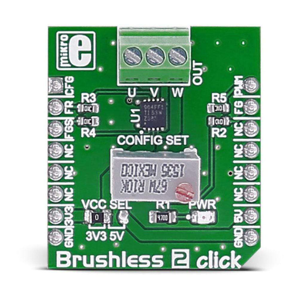
Carte Brushless 2 Click
Overview
Le Brushless 2 Click Board™ est équipé du contrôleur de moteur BLDC DRV10964 avec un étage de sortie intégré. Le Click Board™ est conçu pour fonctionner sur une alimentation 3,3 V ou 5 V.
Il communique avec le microcontrôleur cible via les broches suivantes sur MikroBUS : AN, RST, CS, PWM, INT.
The Brushless 2 Click Board™ carries the DRV10964 BLDC motor controller with an integrated output stage from Texas Instruments. The click is designed to run on either 3.3V or 5V power supply. It communicates with the target microcontroller over the following pins on the mikroBUS™ line: AN, RST, CS, PWM, INT.
How Does The Brushless 2 Click Board™ Work?
A 3 wire BLDC motor can be connected over the screw terminals; speed is controlled through PWM pin on the mikroBUS™ line. The Brushless 2 Click Board™ also has feedback on the interrupt pin (INT), so you can see exactly how fast the motor is going.
DRV10964 MOTOR DRIVER FEATURES
The DRV10964 is a three-phase sensorless motor driver with integrated power MOSFETs. It is specifically designed for high-efficiency, low-noise and low-external component count motor drive applications. The proprietary sensorless windowless 180° sinusoidal control scheme offers ultra-quiet motor drive performance.
The DRV10964 contains an intelligent lock detect function, combined with other internal protection circuits to ensure safe operation.
SPECIFICATIONS
Type | Brushless |
Applications | The automotive industry, drones (because of the good power-to weight ratio of brushless motors), computers, medical equipment, HVAC systems, small home appliances, robotics, battery powered systems, small cooling fans in computers, toys, etc. |
On-board modules | DRV10964 5-V, three-phase sinusoidal sensorless BLDC motor driver |
Key Features | Input voltage range 2.1 to 5.5 V |
Interface | GPIO,PWM |
Compatibility | mikroBUS |
Click board size | S (28.6 x 25.4 mm) |
Input Voltage | 3.3V or 5V |
PINOUT DIAGRAM
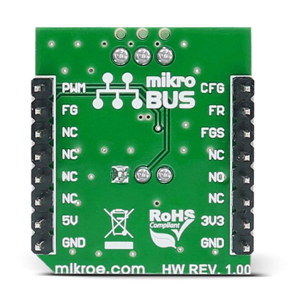
This table shows how the pinout on the Brushless 2 Click Board™ corresponds to the pinout on the mikroBUS™ socket (the latter shown in the two middle columns).
Notes | Pin | Pin | Notes | ||||
---|---|---|---|---|---|---|---|
Resistor setting for configuring the handoff threshold sense | CFG | 1 | AN | PWM | 16 | PWM | Speed control input |
Motor direction selection | FR | 2 | RST | INT | 15 | NC | |
Speed indicator selector | FGS | 3 | CS | TX | 14 | NC | |
NC | 4 | SCK | RX | 13 | NC | ||
NC | 5 | MISO | SCL | 12 | NC | ||
NC | 6 | MOSI | SDA | 11 | NC | ||
Power supply | +3.3V | 7 | 3.3V | 5V | 10 | +5V | Power supply |
Ground | GND | 8 | GND | GND | 9 | GND | Ground |
JUMPERS AND SETTINGS
Designator | Name | Default Position | Default Option | Description |
---|---|---|---|---|
JP1 | PWR.SEL. | Left | 3V3 | Power supply selection, left position 3V3, right position 5V |
Software Support
Code examples for the Brushless 2 Click Board™, written for MikroElektronika hardware and compilers are available on Libstock.
CODE SNIPPET
This code example shows how to change the speed and direction of the motor by pressing buttons on the development board.
01 uint8_t const maxPwmDuty = 255; 02 uint8_t currentDuty = 20 ; 03 uint8_t oldstate = 0; 04 05 void systemInit() 06 { 07 ANCON0 = 0x00; 08 ANCON1 = 0x00; 09 ANCON2 = 0x00; 10 PWM2_Init(5000); 11 PWM2_Start(); 12 PWM2_Set_Duty(currentDuty); 13 MOTOR_DIR_PIN_Direction = 0; 14 } 15 16 void Brushless_2_Init() 17 { 18 MOTOR_DIR_PIN = 1; 19 } 20 21 void Brushless_2_Task() 22 { 23 if (Button(&PORTB, 1, 1, 1)) 24 { 25 currentDuty++; 26 PWM2_Set_Duty(currentDuty); 27 if (currentDuty > maxPwmDuty) 28 currentDuty = 0; 29 30 } 31 32 if (Button(&PORTB, 5, 1, 1)) 33 { 34 oldstate = 1; 35 } 36 if (oldstate && Button(&PORTB, 5, 1, 0)) 37 { 38 MOTOR_DIR_PIN = ~MOTOR_DIR_PIN; 39 oldstate = 0; 40 } 41 } 42 43 void main() 44 { 45 systemInit(); 46 Brushless_2_Init(); 47 48 while( 1 ) 49 { 50 Brushless_2_Task(); 51 } 52 }
Frequently Asked Questions
Have a Question?
Be the first to ask a question about this.