


Mikroelektronika d.o.o.
Tableau à clic BLE 5
Tableau à clic BLE 5
SKU: MIKROE-4120
Impossible de charger la disponibilité du service de retrait
Overview
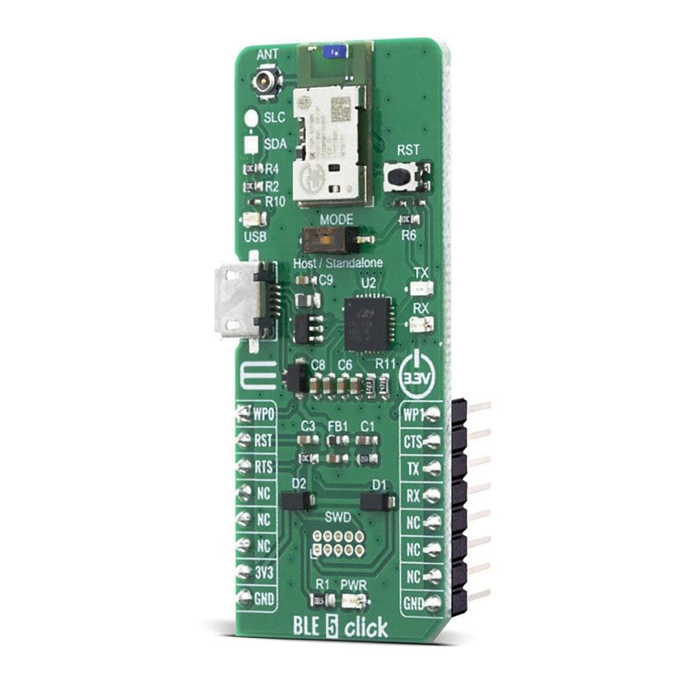
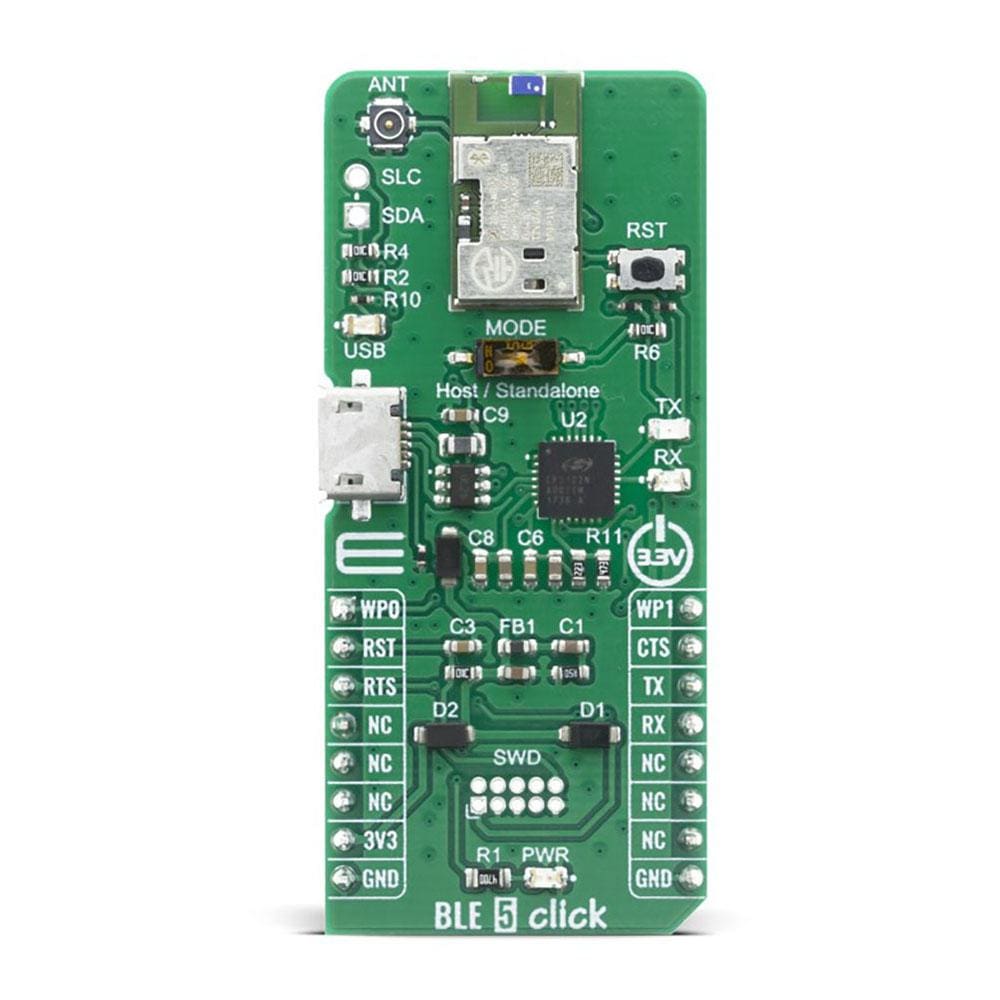
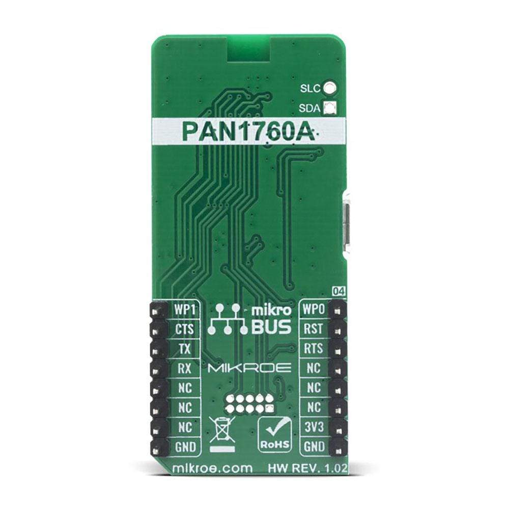
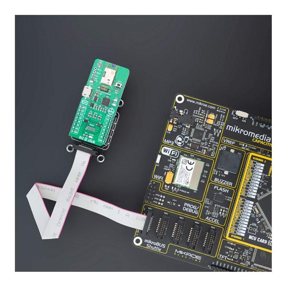
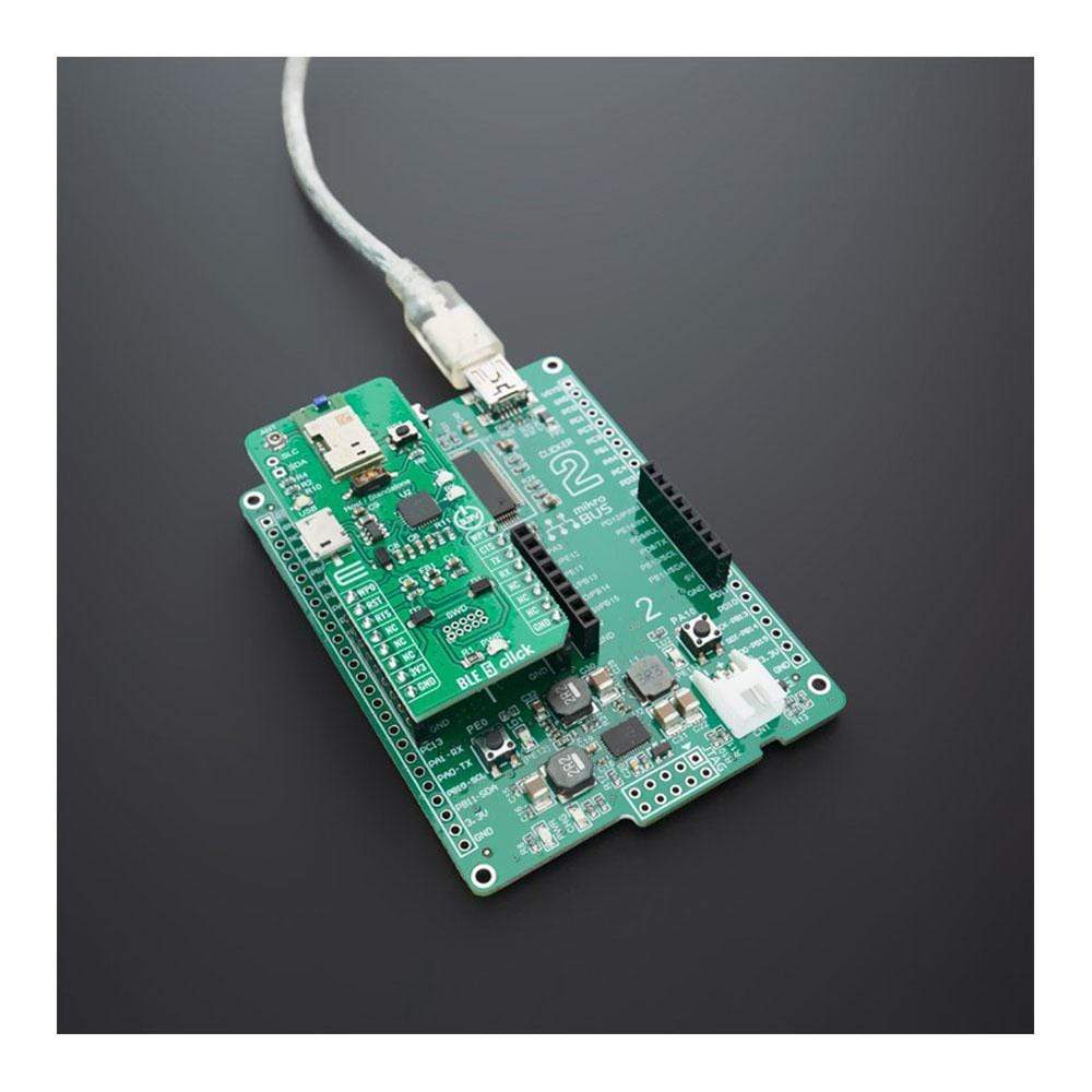
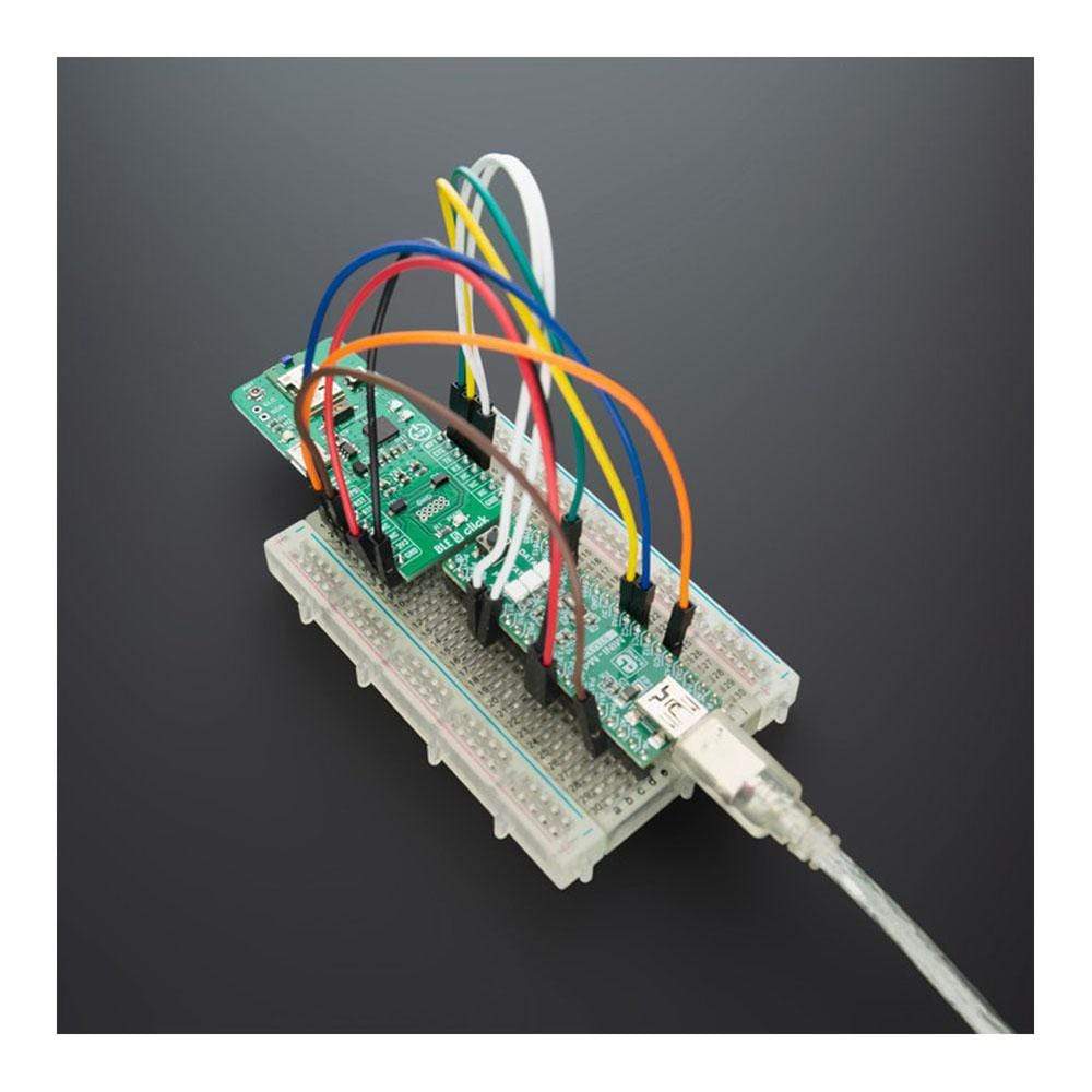
The BLE 5 Click Board™ provides BT/BLE connectivity for any embedded application. The BLE 5 Click Board™ is based on the PAN1760A, a module from Panasonic. The Click Board™ with small Bluetooth Low Energy module for easy integration of Bluetooth Low Energy connectivity (BLE) into various electronic devices. Our board is coming with a module already pre-programmed for AT command mode and can be controlled over the UART interface, in case you need this module to work in Host or Stand-Alone mode a new firmware needs to be applied.
Given its features, the BLE 5 Click Board™ can be used for health, sports, and wellness devices as well as Industrial, home, and building automation; and smartphone, tablet, and PC accessories.
Downloads
La carte BLE 5 Click Board™ fournit une connectivité BT/BLE pour toute application embarquée. La carte BLE 5 Click Board™ est basée sur le PAN1760A, un module de Panasonic. La carte Click Board™ avec un petit module Bluetooth Low Energy pour une intégration facile de la connectivité Bluetooth Low Energy (BLE) dans divers appareils électroniques. Notre carte est livrée avec un module déjà préprogrammé pour le mode de commande AT et peut être contrôlée via l'interface UART. Si vous avez besoin que ce module fonctionne en mode hôte ou autonome, un nouveau micrologiciel doit être appliqué.
Compte tenu de ses caractéristiques, le BLE 5 Click Board™ peut être utilisé pour les appareils de santé, de sport et de bien-être ainsi que pour l'automatisation industrielle, domestique et des bâtiments, ainsi que pour les accessoires pour smartphones, tablettes et PC.
| General Information | |
|---|---|
Part Number (SKU) |
MIKROE-4120
|
Manufacturer |
|
| Physical and Mechanical | |
Weight |
0.02 kg
|
| Other | |
EAN |
8606018717507
|
Frequently Asked Questions
Have a Question?
Be the first to ask a question about this.