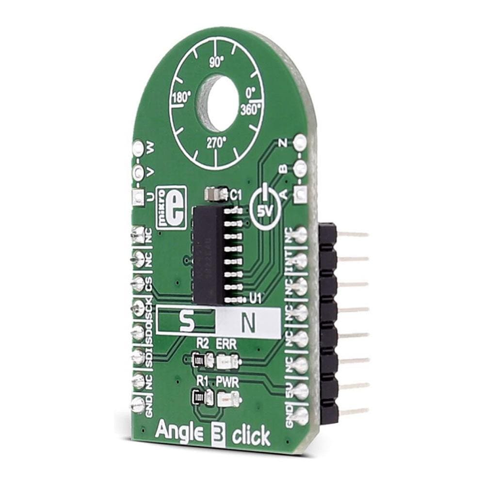
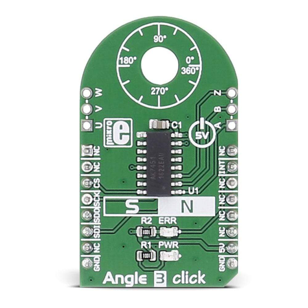
Planche à clic Angle 3
Overview
Le Click Board™ Angle 3 est équipé du capteur d'angle de rotation magnétique AK7451. Le Click Board™ est conçu pour fonctionner sur une alimentation 5 V.
Il communique avec le microcontrôleur cible via l'interface SPI, avec des fonctionnalités supplémentaires fournies par la broche INT sur la ligne MikroBUS.
The Angle 3 Click Board™ is based on the AK7451, a magnetic rotational angle sensor. The click is designed to run on a 5V power supply. It communicates with the target microcontroller over SPI interface, with additional functionality provided by the INT pin on the mikroBUS™ line.
Angle 3 click can be used for non-contact rotation angle measurement.
AK7451 FEATURES
The AK7451 is a magnetic rotational angle sensor with a built-in Hall element.
By detecting the magnetic field vector parallel to the IC surface, the AK7451 outputs the absolute angular position of the magnet and the relative angular position.
Through the transverse magnetic field detection method, using a magnetic flux concentrator, the AK7451 has excellent axial misalignment immunity.
How Does The Angle 3 Click Board™ Work?
The host microcontroller sends the request for measuring the angle rotation via the SPI interface. The AK7451 sensor responds with the measured data.
There are 3 output pins on board (A, B, Z) where the IC outputs pulses for the encoder feature and the 3 output pins (U, V, W) where the IC outputs pulses for the BLDC motor drive.
SPECIFICATIONS
Type | Magnetic |
Applications | The Angle 3 Click Board™ is suitable for various motor drive and encoder applications |
On-board modules | AK7451 zero latency angle sensor |
Key Features | 12bit angle resolution, less than ±0.6 deg. angle accuracy at 25 ºC, maximum tracking speed : 333 rps (20,000 rpm) |
Interface | SPI |
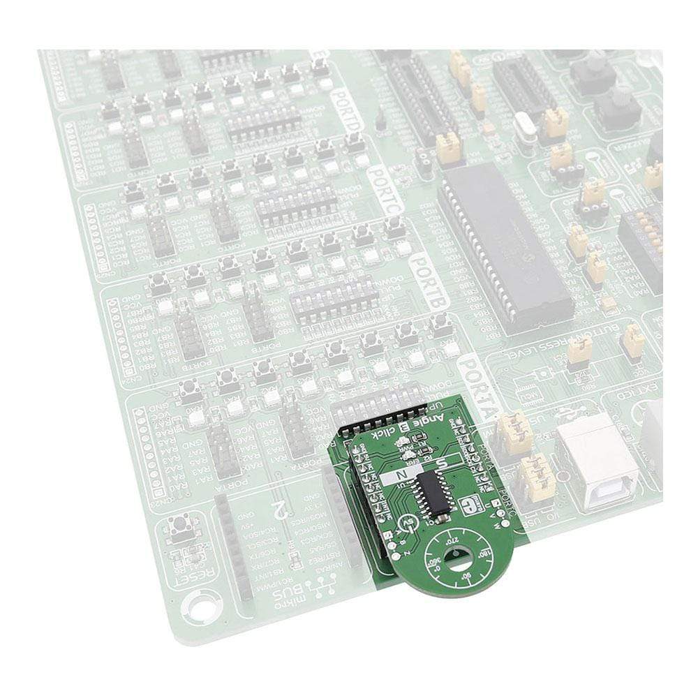
Compatibility | mikroBUS |
Click board size | M (42.9 x 25.4 mm) |
Input Voltage | 5V |
PINOUT DIAGRAM
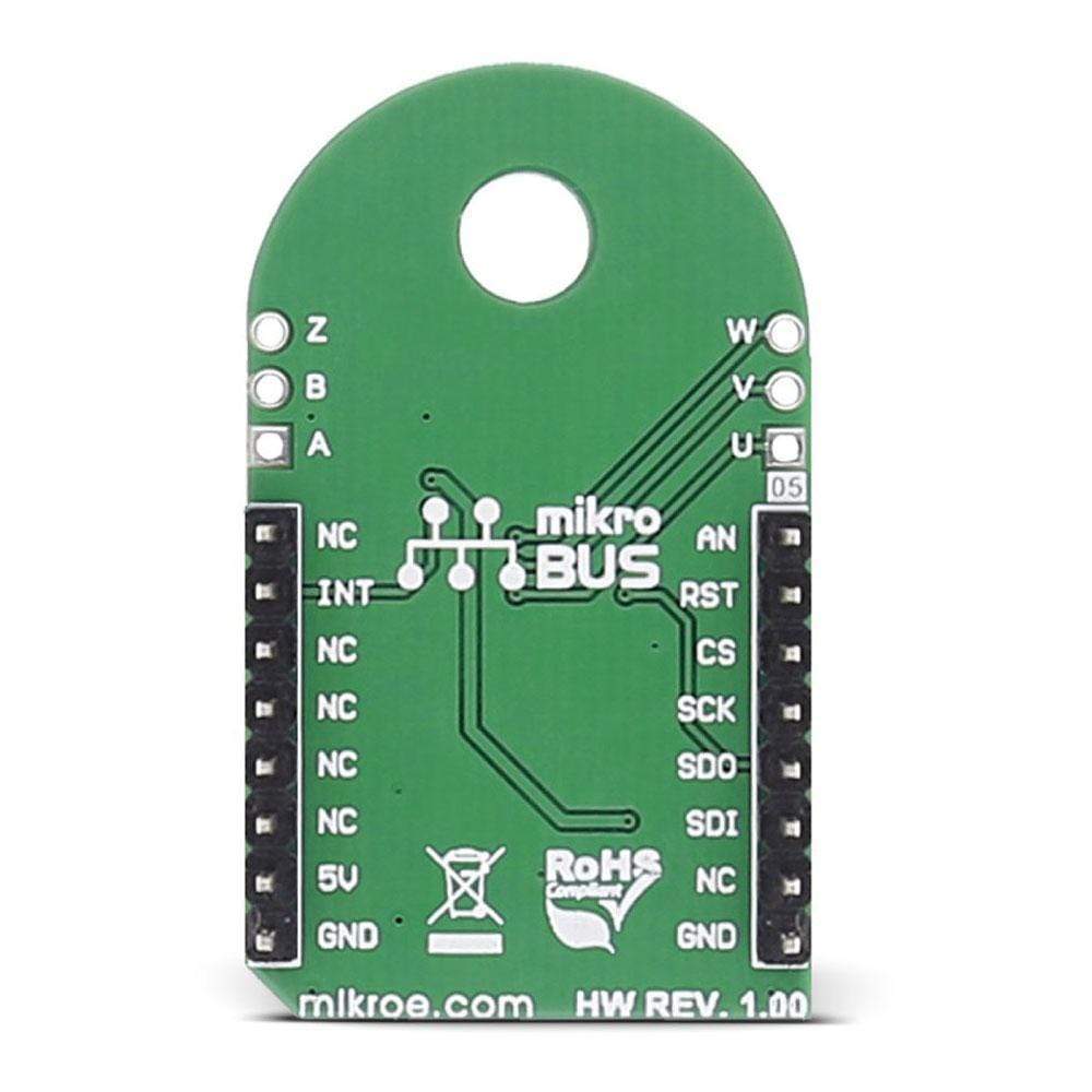
This table shows how the pinout on the Angle 3 Click Board™ corresponds to the pinout on the mikroBUS™ socket (the latter shown in the two middle columns).
Notes | Pin | Pin | Notes | ||||
---|---|---|---|---|---|---|---|
NC | 1 | AN | PWM | 16 | NC | ||
NC | 2 | RST | INT | 15 | INT | Interrupt | |
Chip select | CS | 3 | CS | TX | 14 | NC | |
SPI clock | SCK | 4 | SCK | RX | 13 | NC | |
Slave data out for SPI | SDO | 5 | MISO | SCL | 12 | NC | |
Slave data in for SPI | SDI | 6 | MOSI | SDA | 11 | NC | |
NC | 7 | 3.3V | 5V | 10 | +5V | Power supply | |
Ground | GND | 8 | GND | GND | 9 | GND | Ground |
Software Support
Code examples for the Angle 3 Click Board™, written for MikroElektronika hardware and compilers are available on Libstock.
CODE SNIPPET
This code demonstrates the usage of the Angle 3 Click Board™ driver on an STM ARM board. After the initialization, data from the click is being read, converted, and displayed via UART, in a loop.
01 // Main function. 02 void main() 03 { 04 uint16_t angleData; // Angle data read from Angle3. 05 uint16_t angleDataDegrees; // Angle data converted to degrees. 06 uint8_t buffer[20]; // Buffer for characters to send via UART. 07 08 // Initialize the system. 09 systemInit(); 10 11 // First write to UART. 12 UART1_Write_Text("Start"); 13 UART1_Write(13); 14 UART1_Write(10); 15 16 // Main loop. 17 while( 1 ) 18 { 19 // Some delay. 20 Delay_ms(1000); 21 22 // Read angle data and convert. 23 angleData = ANGLE3_readAngleData(); 24 25 // Check the error bit. 26 if ((angleData & _ANGLE3_ERR_BITMASK) == 0) 27 { 28 // Send error message via UART. 29 UART1_Write_Text(" error"); 30 31 // Continue with next loop iteration. 32 continue; 33 } 34 35 // Convert angle data to degrees. 36 angleData &= 0x0FFF; // Actual data is in the lower 12 bits. 37 angleDataDegrees = ANGLE3_calculateDegrees(angleData); 38 39 // Send angle data via UART. 40 IntToStr(angleDataDegrees, buffer); 41 UART1_Write_Text(buffer); 42 } 43 }
Frequently Asked Questions
Have a Question?
Be the first to ask a question about this.