

Picotest
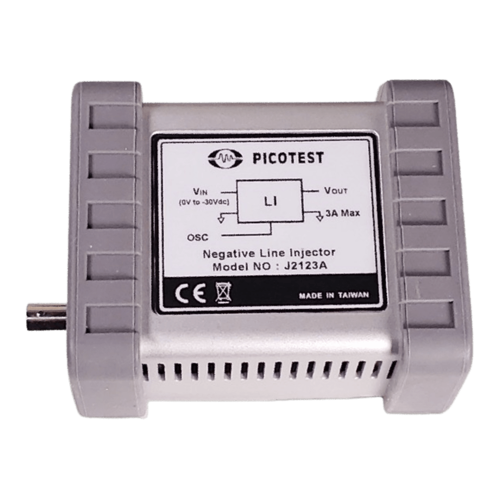
Picotest J2123A Negative Voltage PSRR Injector - 10Hz-50MHz Line Injector
Picotest J2123A Negative Voltage PSRR Injector - 10Hz-50MHz Line Injector
SKU: J2123A
Couldn't load pickup availability

Key Features
Overview
Downloads
Why Engineers Choose The Picotest J2123A Negative Voltage PSRR Injector - 10Hz-50MHz Line Injector
Dual-Supply System Testing
Audio Amplifier Validation
Precision Reference Circuits
Professional Negative Voltage PSRR Testing Made Simple
The Picotest J2123A Negative Voltage PSRR Injector transforms complex power supply testing into straightforward measurements. Specifically designed for negative voltage systems, this passive line injector enables accurate Power Supply Rejection Ratio (PSRR), Power Supply Modulation Ratio (PSMR), and Common-Mode Rejection Ratio (CMRR) measurements across a wide frequency range.
Key Applications
Essential for testing negative voltage regulators, audio amplifiers, and precision reference circuits. The J2123A excels in applications requiring low-noise modulation of negative DC power sources, making it indispensable for engineers working with dual-supply systems or negative voltage rails.
Technical Specifications
| Parameter | Specification |
|---|---|
| Maximum DC Input Voltage | -30VDC |
| Maximum Continuous Current | 3A |
| Maximum Voltage Drop | 3VDC |
| 3dB Frequency Response | 20Hz-20MHz |
| Useable Frequency Response | 10Hz-50MHz |
| Recommended Injection Signal | -20dBm to 10dBm |
| Temperature Range | 0-50°C |
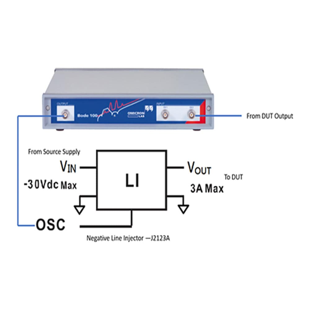
Wiring Quick-Start
Critical Polarity Warning
The J2123A contains a polarised internal capacitor and will be damaged if input voltage is reversed. In negative voltage systems, the return jack (ground/0V) must be more positive than the MINUS SUPPLY connection.
Connect your negative power supply to the J2123A input terminals with correct polarity: ground (return) to the positive terminal, negative voltage to the negative terminal. Connect the modulation source (such as a Bode 100 or network analyser) to the OSC input. The J2123A output connects directly to your device under test.
Measurement Setup
For single-supply PSRR measurements, connect Channel 1 of your analyser to the J2123A input, Channel 2 to the output. The ratio measurement directly provides PSRR data. For dual-supply audio amplifier testing, use the J2123A in conjunction with a J2120A for comprehensive positive and negative rail modulation.
Performance Characteristics
Voltage drop and output resistance follow the relationship: V(I) = 2.312 × I^0.055 + 0.090I, where current is in amperes. This passive design ensures optimum performance with minimal noise injection while maintaining wide bandwidth capability.
Remote sensing capability allows compensation for the line injector's voltage drop when using laboratory power supplies with adequate compliance range.
Frequently Asked Questions
Have a Question?
-
Is the J2123A suitable for production testing environments?
Absolutely. The passive design ensures reliability, whilst the wide frequency range covers most product requirements. The device withstands repeated use and provides consistent measurements essential for production quality control.
-
What test equipment do I need in addition to the J2123A?
A network analyser or signal generator for modulation, a negative voltage power supply, and appropriate cables. Optional equipment includes current probes for impedance measurements and the remote sense board for improved voltage regulation.
-
How does the J2123A compare to using injection transformers?
The J2123A handles DC current without saturation, unlike injection transformers which fail with even small DC currents (5mA or less). This makes the J2123A essential for PSRR measurements where injection transformers would be damaged or provide inaccurate results.
-
What safety precautions should I observe when using the J2123A?
Never exceed the absolute maximum ratings: -50V DC+AC combined, 3A continuous current, and 50°C operating temperature. Ensure proper grounding and use appropriate personal protective equipment when working with high voltages.
-
Can I measure input impedance with the J2123A?
Yes, when used with a current probe, the J2123A enables input impedance measurements of negative voltage power supplies and DC-DC converters. This is particularly useful for stability analysis and EMI filter design in negative voltage systems.
-
What modulation sources work with the J2123A?
Any network analyser or signal generator with appropriate output level. The J2123A accepts -20dBm to +10dBm signals through its 10kΩ input impedance. Popular choices include the OMICRON Lab Bode 100, Keysight E5061B, and Rohde & Schwarz ZNB series.
-
How do I compensate for the voltage drop across the J2123A?
Use remote sensing if your power supply supports it, or manually adjust the supply voltage to account for the drop. The voltage drop follows V(I) = 2.312 × I^0.055 + 0.090I. Alternatively, use the optional remote sense board for automatic compensation.
-
What happens if I connect the polarity incorrectly?
The J2123A contains a polarised internal capacitor that will be permanently damaged by reverse voltage. Always verify that the return jack (ground) is more positive than the MINUS SUPPLY connection before applying power.
-
Can I use the J2123A with standard laboratory power supplies?
Yes, but ensure correct polarity connections. The ground terminal should be more positive than the negative supply terminal. Many power supplies can be configured for negative output by reversing their connections, making them compatible with the J2123A.
-
What makes the J2123A different from the J2120A line injector?
The J2123A is specifically designed for negative voltage systems with polarised internal components, whilst the J2120A handles positive voltages. The J2123A has lower current capacity (3A vs 5A) but identical frequency response, making it ideal for lower-power negative rail applications.