


Mikroelektronika d.o.o.
SPI Isolator 3 Click Board™
SPI Isolator 3 Click Board™
SKU: MIKROE-4651
Couldn't load pickup availability


Overview
The SPI Isolator 3 Click Board™ is a compact add-on board that contains a digital isolator optimised for a serial peripheral interface. This board features the MAX14483, a 6-channel 3.75kVRMS digital galvanic isolator with a very low propagation delay on the SDI, SDO, and SCLK channels from Maxim Integrated. Besides a second enable control input, which allows MAX14483 to isolate multiple SPI devices, and an auxiliary channel available for passing timing or control signals from the master side to the slave side, the MAX14483 also possesses power monitors provided for both power domains to signal if the opposite side of the isolator is ready for operation.
Thus, the SPI Isolator 3 Click Board™ is suitable for general SPI-bus isolation and industrial, process, building automation, programmable logic controllers, and many more.
Downloads
How Does The SPI Isolator 3 Click Board™ Work?
The SPI Isolator 3 Click Board™ as its foundation uses the MAX14483, a 6-channel 3.75kVRMS digital isolator with a very low propagation delay on the SDI, SDO, and SCLK channels from Analog Devices. It provides galvanic isolation for digital signals transmitted between two ground domains. The device withstands up to 560Vpeak of continuous isolation and up to 3.75kVRMS for up to 60 seconds. The wide supply voltage range of both power pins allows the MAX14483 to be used for level translation and isolation.
The MAX14483 offers low-power operation, high electromagnetic interference immunity, and stable temperature performance through Maxim's proprietary process technology. The device isolates different ground domains and blocks high-voltage/high-current transients from sensitive or human interface circuitry. It also features an internal refresh circuit to ensure output accuracy when an input remains in the same state indefinitely.
The SPI Isolator 3 Click Board™ communicates with MCU using the SPI serial interface with a maximum data rate of 200 Mbps. This Click board™ also comes with a SDO line enable control pin, labelled as OEN and routed on the RST pin of the mikroBUS™ socket, allowing MAX14483 to isolate multiple SPI devices. It also has a red LED indicator labelled as FLT to detect error outputs from other devices.
Besides an auxiliary channel, labelled as AUX, available for passing timing or control signals from the master side to the slave side, the MAX14483 also possesses power monitors for both power domains to signal if the opposite side of the isolator is ready for operation. The FLT and AUX channels are designed to support SPI devices that require control signals beyond the standard 4-wire SPI bus. Each channel is unidirectional; it only passes data in one direction with a maximum data rate of 25Mbps.
The monitor channels (SAA, SBA) are designed to pass DC signals and have significantly longer propagation delays than other channels, meaning they should not be used for data signals. SAA and SBA are set high when their respective opposite side of the isolator has power and is operating normally. When Side A or Side B is not powered, SAA or SBA is set low, and all outputs are set to their default state.
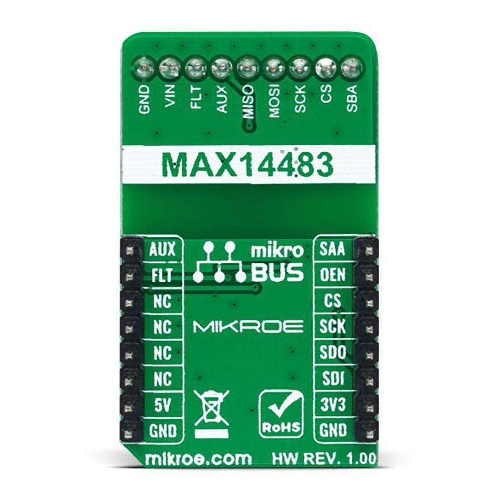
The SPI Isolator 3 Click Board™ can operate with both 3.3V and 5V logic voltage levels selected via the VCC SEL jumper. This way, it is allowed for both 3.3V and 5V capable MCUs to use the SPI communication lines properly. However, the Click board™ comes equipped with a library containing easy-to-use functions and an example code that can be used, as a reference, for further development.
SPECIFICATIONS
| Type | Isolators, SPI |
| Applications | Can be used for general SPI-bus isolation and the industrial, process, and building automation, in programmable logic controllers, and many more. |
| On-board modules | MAX14483 - 6-channel 3.75kVRMS digital isolator with a very low propagation delay on the SDI, SDO, and SCLK channels from Maxim Integrated |
| Key Features | Low power consumption, 6 isolated channels, low propagation delay on SCLK, SDI, and SDO lines, robust galvanic isolation of digital signals, shared interrupt feature, auxiliary channel for timing or control, and more. |
| Interface | SPI |
| Compatibility | mikroBUS |
| Click board size | M (42.9 x 25.4 mm) |
| Input Voltage | 3.3V or 5V,External |
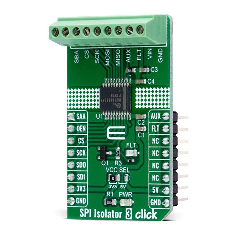
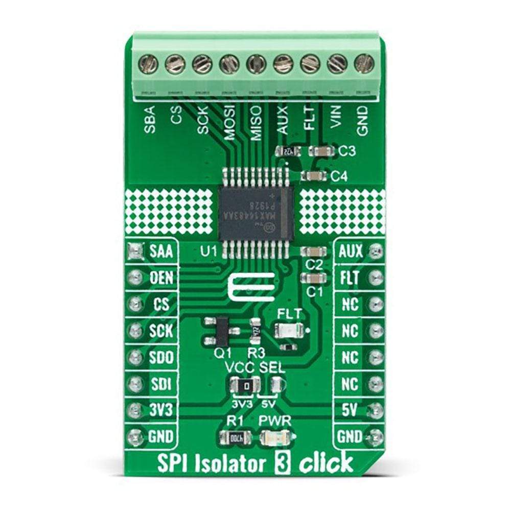
PINOUT DIAGRAM
This table shows how the pinout of the SPI Isolator 3 Click Board™ corresponds to the pinout on the mikroBUS™ socket (the latter shown in the two middle columns).
| Notes | Pin | Pin | Notes | ||||
|---|---|---|---|---|---|---|---|
| Power Monitoring | SAA | 1 | AN | PWM | 16 | AUX | Auxiliary Signal for Timing or Control |
| SPI SDO Signal Enable | OEN | 2 | RST | INT | 15 | FLT | Interrupt |
| SPI Chip Select | CS | 3 | CS | RX | 14 | NC | |
| SPI Clock | SCK | 4 | SCK | TX | 13 | NC | |
| SPI Data OUT | SDO | 5 | MISO | SCL | 12 | NC | |
| SPI Data IN | SDI | 6 | MOSI | SDA | 11 | NC | |
| Power Supply | 3.3V | 7 | 3.3V | 5V | 10 | 5V | Power Supply |
| Ground | GND | 8 | GND | GND | 9 | GND | Ground |
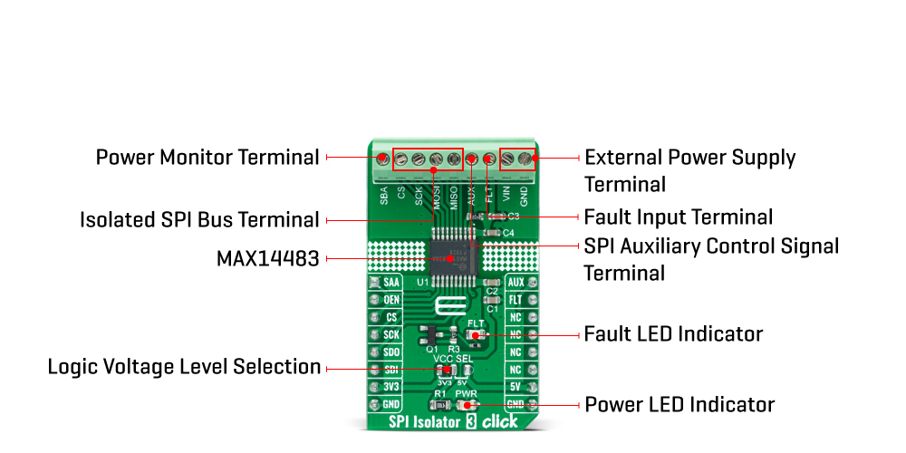
ONBOARD SETTINGS AND INDICATORS
| Label | Name | Default | Description |
|---|---|---|---|
| LD1 | PWR | - | Power LED Indicator |
| LD2 | FLT | - | Fault LED Indicator |
| JP1 | VCC SEL | Left | Logic Level Voltage Selection 3V3/5V: Left position 3V3, Right position 5V |
SPI ISOLATOR 3 CLICK ELECTRICAL SPECIFICATIONS
| Description | Min | Typ | Max | Unit |
|---|---|---|---|---|
| Supply Voltage VCC | 3.3 | - | 5 | V |
| External Supply Voltage VIN | 1.71 | - | 5.5 | V |
| Isolation Voltage | - | - | 3750 | Vrms |
| Data Rate | - | - | 200 | Mbps |
| Operating Temperature Range | -40 | +25 | +125 | °C |
| General Information | |
|---|---|
Part Number (SKU) |
MIKROE-4651
|
Manufacturer |
|
| Physical and Mechanical | |
Weight |
0.02 kg
|
| Other | |
EAN |
8606027382833
|
Frequently Asked Questions
Have a Question?
Be the first to ask a question about this.