

Mikroelektronika d.o.o.
SPI Extend Click Board™
SPI Extend Click Board™
SKU: MIKROE-4184
Couldn't load pickup availability


Overview
The SPI Extend Click Board™ is a compact add-on board for applications that require extending the SPI communication bus over a long distance. This board features the LTC4332, an SPI slave extender device, from Analog Devices. Using a ±60V fault protected differential transceiver, the LTC4332 can transmit SPI data, including an interrupt signal, up to 2MHz over two twisted-pair cables. The extended common-mode range and high common-mode rejection on the differential link provide tolerance to large ground differences between nodes. This Click Board™ also provides a control interface using a separate slave select for configuration and fault monitoring. All these features make SPI Extend Click an excellent choice for various applications that require extending the SPI bus over a long distance, such as industrial control, sensor installations, lighting and sound system control, and more.
The SPI Extend Click Board™ is supported by a mikroSDK compliant library, which includes functions that simplify software development. This Click Board™ comes as a fully tested product, ready to be used on a system equipped with the mikroBUS™ socket.
Downloads
How Does The SPI Extend Click Board™ Work?
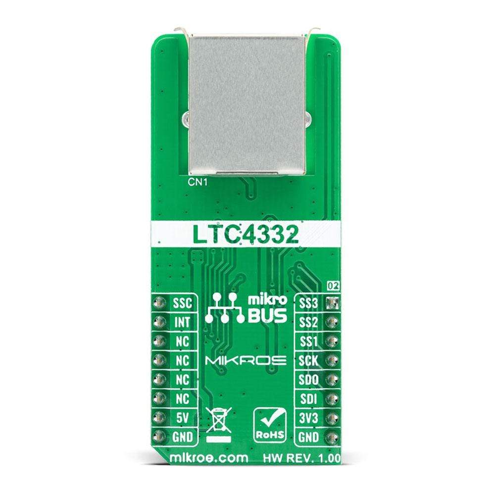
The SPI Extend Click Board™ is based on LTC4332, a 2MHz point-to-point SPI bus extender designed for operation in high noise industrial environments, IC from Analog Devices. The SPI bus is extended over two twisted pairs by ±60V fault protected differential transceivers. The LTC4332's extended 25V common-mode voltage range allows it to bridge across different ground potentials. This Click board™ has 3 extended slave selects (SS1, SS2, SS3), has separate programmable SPI modes, and also supports external galvanic isolation on the link. Slave select output pin SS1 is used as a standard CS pin in SPI communication, while the other two pins SS2 and SS3 are used as GPIO output pins on the local side in terms of mikroBUS standard.
NOTE: In order to achieve the complete functionality of this Click board™, it is necessary to use crossover twisted-pair cables with RJ45 connectors, the same ones used with Ethernet devices.
Alongside with it's extended functionalities, this Click board™ also supports local to remote control and interrupt functions. Using an integrated high-performance differential transceiver for link communication, a local SPI master can access remote slave devices up to 1200m using differential-pair type cabling. Because of the dual functionality of the SPI Extend Click, the user needs to set the mode of operation of the Click board™, which is adjusted by setting onboard MODE SEL switch to the appropriate position (set low for local SPI slave mode or set high for SPI master mode).
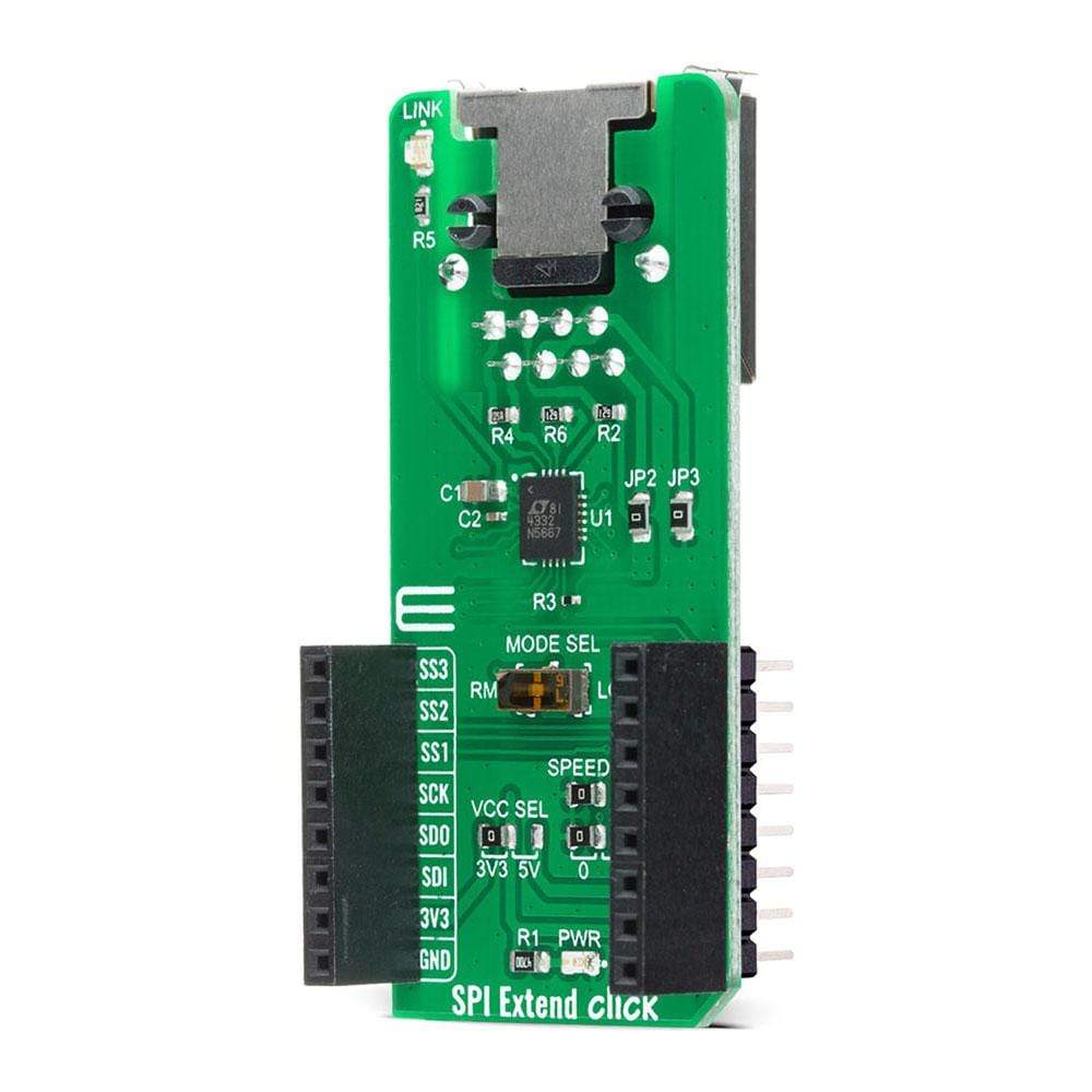
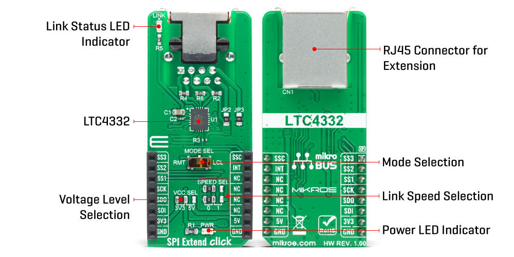
The SPI Extend Click Board™ communicates with MCU using the SPI serial interface that supports SPI modes (0,0) and (1,1) only, with a maximum SPI frequency of 2 MHz. The LTC4332 provides a separate slave select pin, SSC, that allows a user to access the internal control interface for configuration and monitoring. It also has an interrupt pin (INT) that acts as an open-drain output in local mode and an input in remote mode. On the remote side, INT is an input pin that can be connected to remote SPI devices, while on the local side INT operates as an open-drain output that can be connected to a shared local interrupt line. In addition to the mode selection, there are SPEED SEL jumpers that select the link baud rate and the remote SCK timing parameters, and Link Status LED indicator that is active when the device successfully establishes link communication between the local and remote sides.
The SPI Extend Click Board™ uses the SPI communication interface with both 3.3V and 5V. The onboard SMD jumper labelled as VCC SEL allows voltage selection for interfacing with both 3.3V and 5V MCUs. More information about the LTC4332's functionality, electrical specifications, and typical performance can be found in the attached datasheet. However, the Click board™ comes equipped with a library that contains easy to use functions and a usage example that may be used as a reference for the development.
SPECIFICATIONS
| Type | SPI |
| Applications | An excellent choice for various applications that require extending the SPI bus over a long distance, such as industrial control, sensor installations, lighting and sound system control, and more. |
| On-board modules | The SPI Extend Click Board™ is based on LTC4332, a 2MHz point-to-point SPI bus extender designed for operation in high noise industrial environments, IC from Analog Devices. |
| Key Features | Operation over long distances, extended slave selects, overvoltage protection, low power consumption... |
| Interface | GPIO,SPI |
| Compatibility | mikroBUS |
| Click board size | L (57.15 x 25.4 mm) |
| Input Voltage | 3.3V or 5V |
PINOUT DIAGRAM
This table shows how the pinout of the SPI Extend Click Board™ corresponds to the pinout on the mikroBUS™ socket (the latter shown in the two middle columns).
| Notes | Pin | Pin | Notes | ||||
|---|---|---|---|---|---|---|---|
| Slave Select 3 | SS3 | 1 | AN | PWM | 16 | SSC | Control Interface Select |
| Slave Select 2 | SS2 | 2 | RST | INT | 15 | INT | Interrupt |
| SPI Chip Select | SS1 | 3 | CS | RX | 14 | NC | |
| SPI Clock | SCK | 4 | SCK | TX | 13 | NC | |
| SPI Data OUT | SDO | 5 | MISO | SCL | 12 | NC | |
| SPI Data IN | SDI | 6 | MOSI | SDA | 11 | NC | |
| Power Supply | 3.3V | 7 | 3.3V | 5V | 10 | 5V | Power Supply |
| Ground | GND | 8 | GND | GND | 9 | GND | Ground |
ONBOARD SETTINGS AND INDICATORS
| Label | Name | Default | Description |
|---|---|---|---|
| LD1 | PWR | - | Power LED Indicator |
| LD2 | LINK | - | Link Status LED Indicator |
| JP1 | VCC SEL | Left | Power Supply Voltage Selection 3V3/5V: Left position 3V3, Right position 5V |
| JP2 | SPEED SEL | Left | Communication Speed Selection: Left position 0, Right position 1 |
| SW1 | MODE SEL | Right | Local to Remote Control Selection: Left position RMT, Right position LCL |
SPI EXTEND CLICK ELECTRICAL SPECIFICATIONS
| Description | Min | Typ | Max | Unit |
|---|---|---|---|---|
| Supply Voltage | -0.3 | 3.3 | 6 | V |
| SPI Serial Clock Frequency | - | - | 2 | mHz |
| Extension Range | - | - | 1200 | m |
| Operating Temperature Range | 0 | - | 70 | °C |
| General Information | |
|---|---|
Part Number (SKU) |
MIKROE-4184
|
Manufacturer |
|
| Physical and Mechanical | |
Weight |
0.023 kg
|
| Other | |
EAN |
8606027380174
|
Frequently Asked Questions
Have a Question?
Be the first to ask a question about this.