Overview
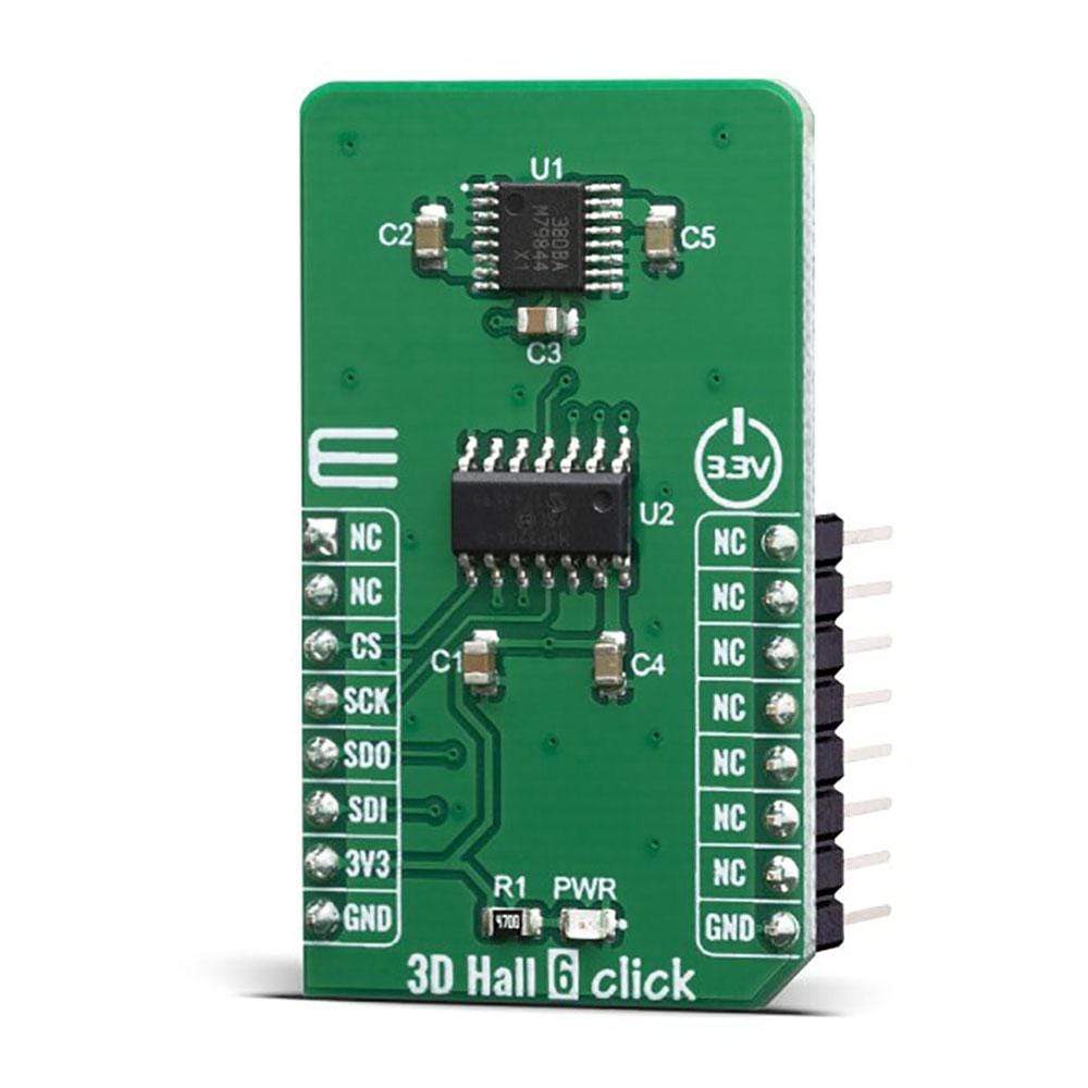
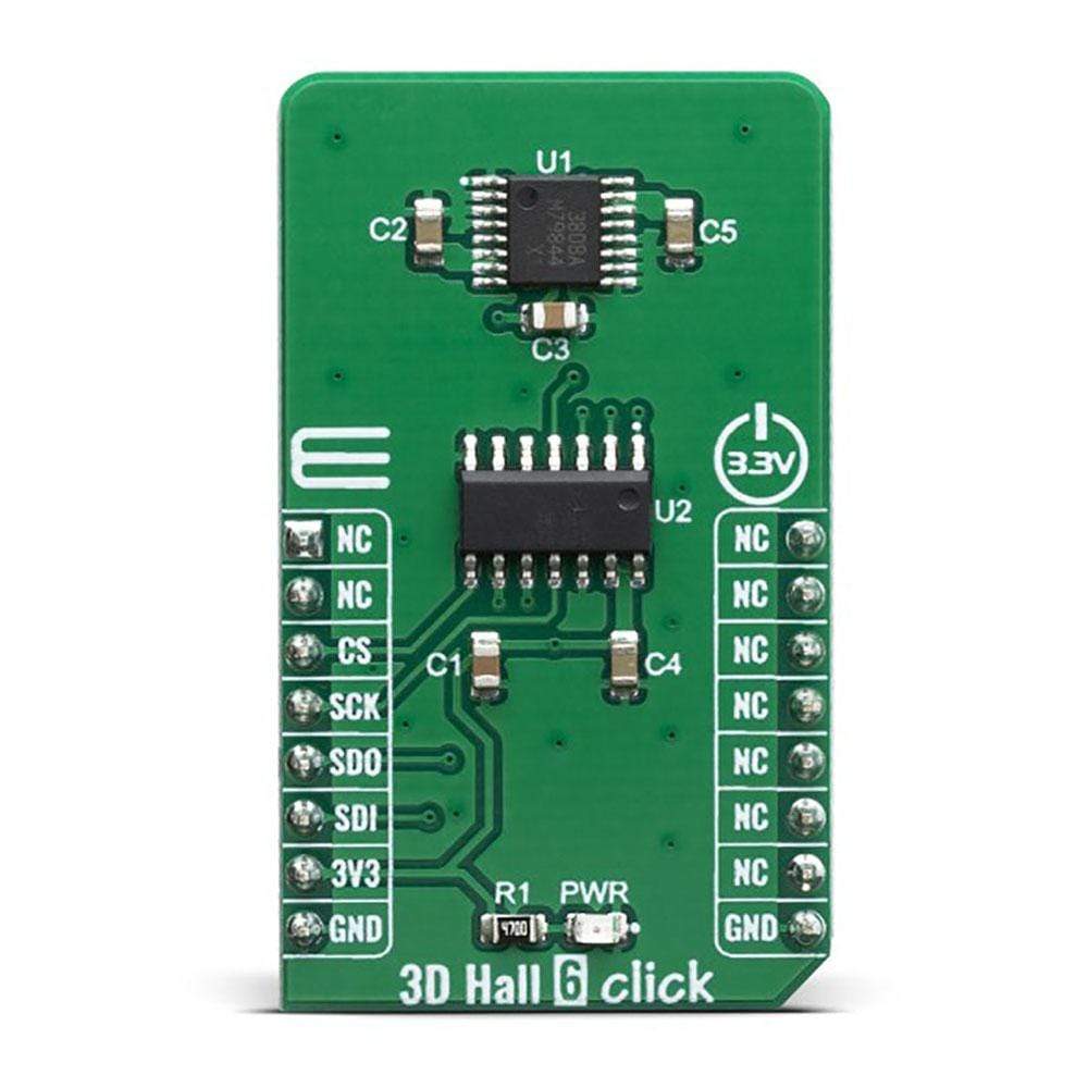
The 3D Hall 6 Click Board™ is a very accurate, magnetic field sensing Click Board™, used to measure the intensity of the magnetic field across three perpendicular axes. It is equipped with the MLX90380, a monolithic contactless sensor IC sensitive to the flux density applied orthogonally and parallel to the IC surface, from Melexis. This IC has a separate Hall sensing element on each axis, which allows a very accurate and reliable measurement of the magnetic field intensity in a 3D space, offering a basis for accurate positional calculations. The 3D Hall 6 click supports the industry-standard SPI communication protocol for communicating with the main MCU.
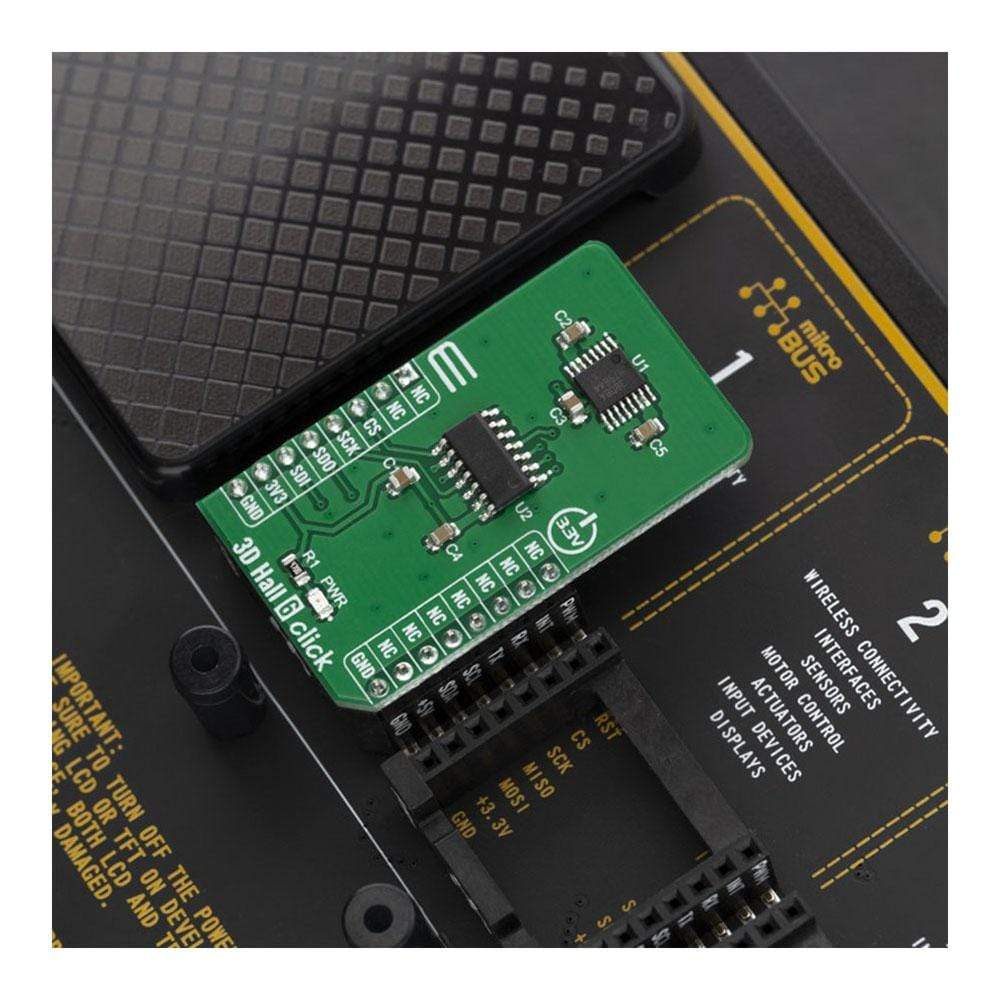
The 3D Hall 6 click is supported by a mikroSDK compliant library, which includes functions that simplify software development. This Click Board™ comes as a fully tested product, ready to be used on a system equipped with the mikroBUS™ socket.
Downloads
The features such as the Triaxis® Hall Technology, Output Refresh Rate (4µs typical) Selectable Magnetic Field Axis (X/Y - X/Z - Z/Y) and wide measurement range all make this sensor a perfect choice for various IoT applications, and because of very good accuracy of the spatial magnetic sensor, perfectly suited for the development of various position sensing applications, contactless knobs, encoders, switches, and potentiometers, or some other type of magnetic field measuring application, based on an accurate spatial sensing.
How Does The 3D Hall 6 Click Board™ Work?
The 3D Hall 6 Click Board™ carries the MLX90380, a monolithic contactless sensor IC sensitive to the flux density applied orthogonally and parallel to the IC surface, from Melexis. This sensor relies on a Hall effect to accurately sense magnetic field changes on three perpendicular axes. The internal magnetic field sensing elements are multiplexed and connected to a pre-amplifier and then to a sine and cosine analog outputs. All of the analog outptts are routed to the MCP3204 - onboard 4-channel 12-Bit A/D converter with SPI interface, from Microchip.
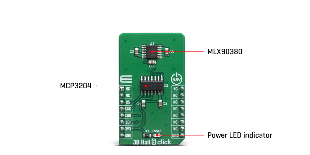
The magnetic sensor has a very low pin count. However, in order to allow reading of the 4 analog inputs on the single Click board™, 3D Hall 6 click have onboard 4-channel, 12-Bit A/D converter, with SPI interface. Thus, the communication interface procedure relies on reading the appropriate registers of the MCP3204.
The MLX90380 contactless sensor also features a powerful programming engine, which allows the sensitivity and filter bandwidth to be programmed to optimally use the ADC input range of the ADC. However, because 3D Hall 6 click have onboard A/D converter, the output voltage of the MLX90380 is matched with the input range of the MCP3204, so the user don't need to do any additional setting.
High-speed dual analog outputs allow the MLX90380 to deliver accurate sine/cosine signals when used with a rotating permanent magnet. The sensor provides raw data output, based on a strength of the magnetic field. The measurement is affected by many factors: slight manufacturing differences between ICs affect the readings, even the slight differences between Hall plates within the same IC might affect the accuracy, although the IC contains highly matched sensing elements. Also, the altitude might affect the readings, as well as temperature changes.
The 3D Hall 6 software library contains simplified functions that allow straight-forward readings to be performed, reducing the steps needed for a proper initialization and configuration of the device.
The 3D Hall 6 Click Board™ can operate with 3.3V MCUs only, it is set to work over the I2C by default, and it is already equipped with the pull-up resistors. It is ready to be used as soon as it is inserted into a mikroBUS™ socket of the development system.
SPECIFICATIONS
| Type | Magnetic |
| Applications | It is perfectly suited for the development of various position sensing applications, contactless knobs, encoders, switches, and potentiometers, or some other type of magnetic field measuring application, based on an accurate spatial sensing. |
| On-board modules | MLX90380, a monolithic contactless sensor IC from Melexis |
| Key Features | The three independent Hall sensor channels allow high accuracy, additional thermal sensor for compensation. The small package case allows a very compact design while offering plenty of features, a programmable interrupt engine, extremely low power consumption, and more |
| Interface | SPI |
| Compatibility | mikroBUS |
| Click board size | M (42.9 x 25.4 mm) |
| Input Voltage | 3.3V |
PINOUT DIAGRAM
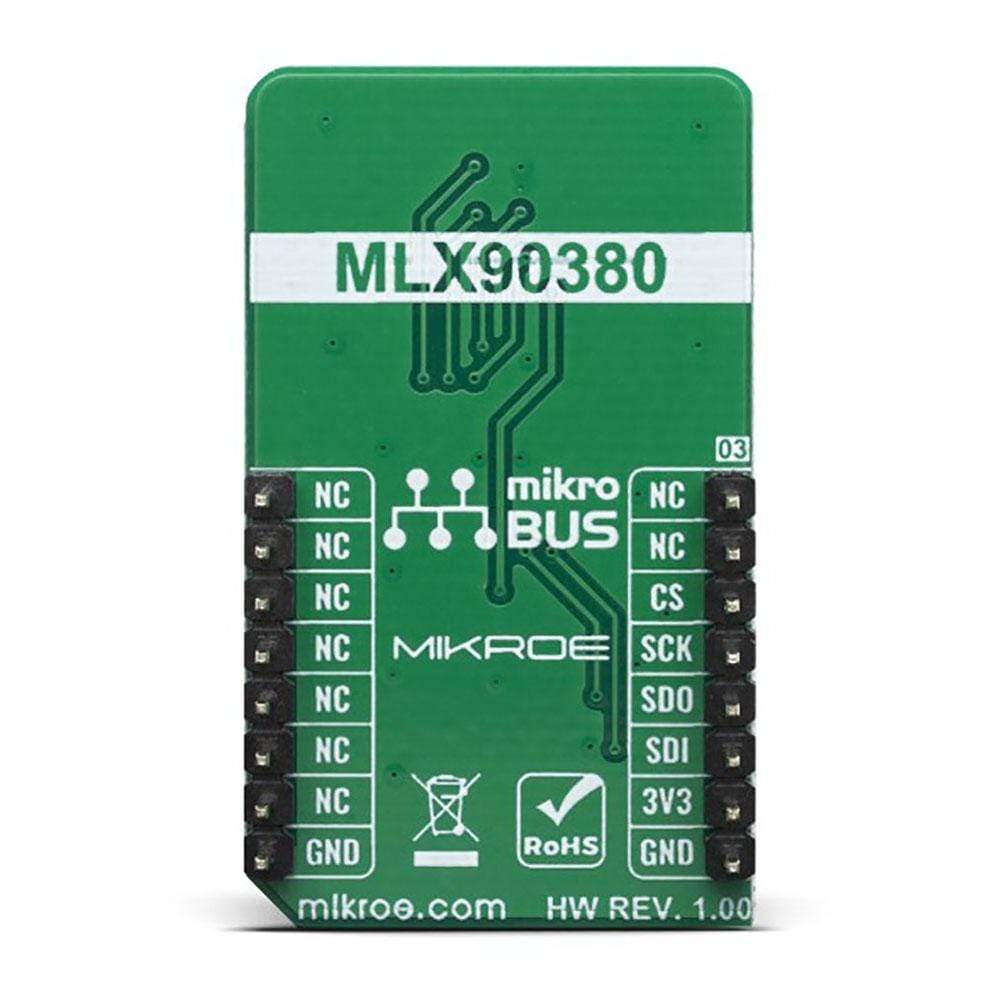
This table shows how the pinout on 3D Hall 6 click corresponds to the pinout on the mikroBUS™ socket (the latter shown in the two middle columns).
| Notes | Pin |  |
Pin | Notes | |||
|---|---|---|---|---|---|---|---|
| NC | 1 | AN | PWM | 16 | NC | ||
| NC | 2 | RST | INT | 15 | NC | ||
| SPI Chip Enable | CS | 3 | CS | RX | 14 | NC | |
| SPI Clock | SCK | 4 | SCK | TX | 13 | NC | |
| SPI SDO | SDO | 5 | MISO | SCL | 12 | NC | |
| SPI SDI | SDI | 6 | MOSI | SDA | 11 | NC | |
| Power Supply | 3.3V | 7 | 3.3V | 5V | 10 | NC | |
| Ground | GND | 8 | GND | GND | 9 | GND | Ground |
ONBOARD SETTINGS AND INDICATORS
| Label | Name | Default | Description |
|---|---|---|---|
| LD1 | PWR | - | Power LED Indicator |
| General Information | |
|---|---|
Part Number (SKU) |
MIKROE-3764
|
Manufacturer |
|
| Physical and Mechanical | |
Weight |
0.018 kg
|
| Other | |
Country of Origin |
|
HS Code Customs Tariff code
|
|
EAN |
8606018717002
|
Warranty |
|
Frequently Asked Questions
Have a Question?
Be the first to ask a question about this.

