


Mikroelektronika d.o.o.
RTC 7 Click Board™
RTC 7 Click Board™
SKU: MIKROE-2976
Couldn't load pickup availability
Overview
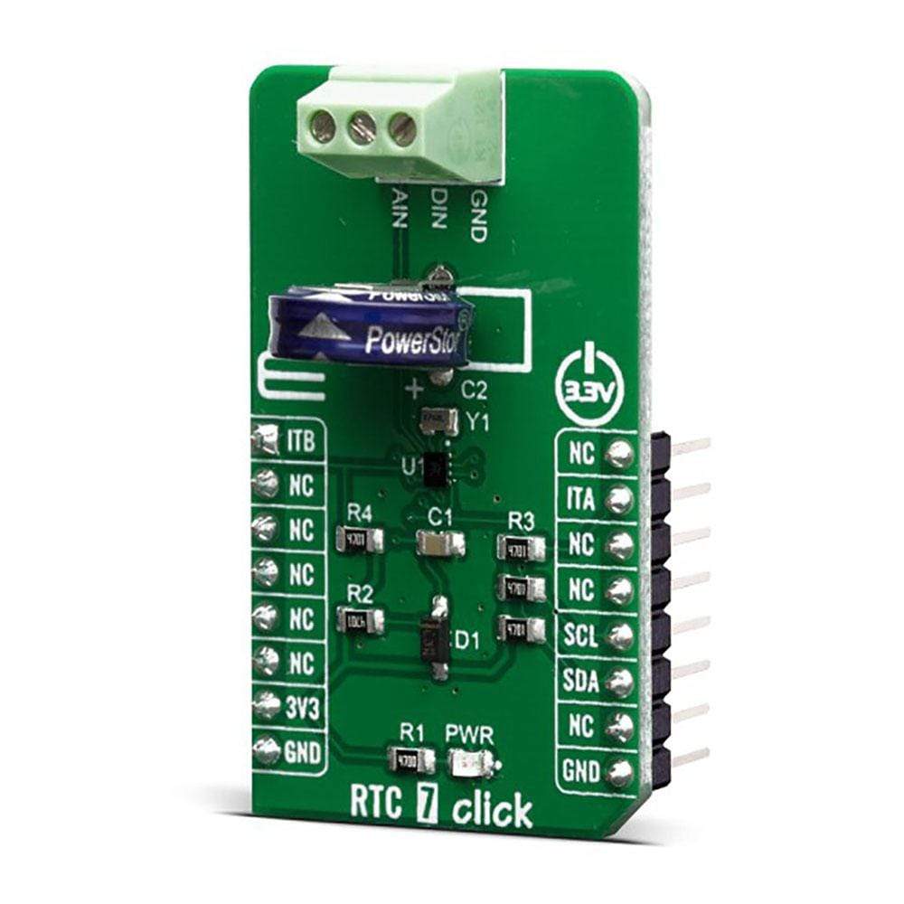
The RTC 7 Click Board™ is a real-time clock module that has an extremely low power consumption, allowing it to be used with a single button cell battery or a supercapacitor, for an extended period of time. The MAX31341B IC built on the RTC 7 Click Board™ is able to output the time in the binary-coded decimal (BCD) format. Integrated, factory calibrated XTAL operating at 32.768 kHz ensures a very low time deviation.
However, the RTC 7 Click Board™ has the onboard external, more precise crystal oscillator too. An advanced interrupt feature allows many different uses such as alarm function, countdown timer function, external event detection function, using analogue and digital inputs and much more.
Downloads
Features such as the ability to be powered over the super capacitor, external event capture pin, BCD time output format, and above all – an extremely low power consumption, make the RTC 7 Click Board™ a perfect solution for the development of the IoT, wearable and portable applications, logging devices, industrial and health-related time metering applications, and all the other applications that require an accurate RTC for their operation.
How Does The RTC 7 Click Board™ Work?
The RTC 7 Click Board™ is based on the MAX31341B, a low-current Real-Time Clock with I2C interface and power management from Maxim Integrated. Thanks to its high integration level, this module provides high time accuracy, with a very low count of external components required. It has a full RTC function, offering programmable counters, alarms, and an interrupt engine with selectable event reporting sources. The small dimension of the MAX31341B module itself, allow it to be used in very space-constrained applications, including wearables, medical equipment, and similar.
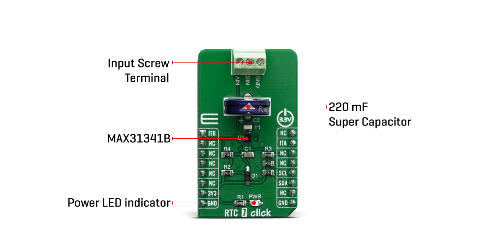
In addition to the MAX31341B, the RTC 7 Click Board™ is equipped with the 220mF super capacitor. By utilizing an automatic backup switch, the IC is able to use an external battery power source when there is no power supply on its main power terminals, thus allowing for uninterrupted operation. Draining as low as 180nA of current, it can be operated with the mentioned supercapacitor almost indefinitely. In addition, a trickle charge system will replenish the super capacitor while the MAX31341B is powered over the main power terminals (VDD, VSS). The voltage of the main power supply can range between 1.6V up to 3.6V.
The MAX31341B uses the I2C communication protocol for the communication with the host MCU. Besides the I2C bus lines, two additional pins are also available on the MAX31341B, INTA and INTB, allowing an interrupt to be reported to the host MCU, but also to capture an external event and marking it with an automatic timestamp. The two mentioned interrupt pins are routed to INT and AN pins of the mikroBUS™ socket, respectively. The user is able to set up standard clock and calendar functions (including seconds, minutes, hours, weekdays, date, months, years with leap year correction), as well as the interrupt functions for the periodic countdown timer, periodic time update, alarm, external event, automatic backup switchover and power on reset (POR) events. All these features are available when the module is operated over the backup power supply (battery).
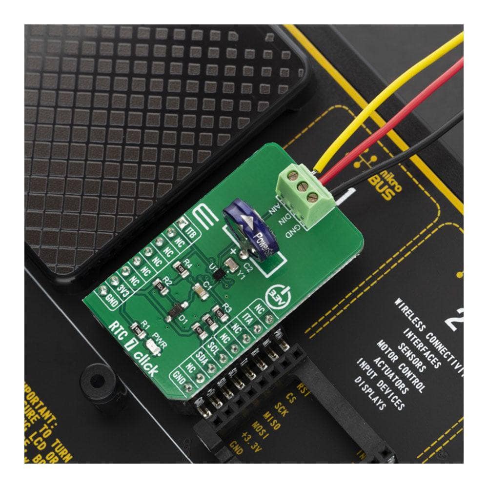
Besides other functions, the RTC 7 Click Board™ has one analog and one digitital external input, labeled AIN and DIN. These universal inputs can be wired to any kind of external trigger, which needs to trigger one of the interrupts. The digital input can be configured to detect rising or falling edge, while the analog input, besides the edge detection, supports the programmable threshold too. For detailed information on interrupts and external triggers, refer to the MAX31341B datasheet.
The RTC 7 Click Board™ is designed to work with 3.3V only. When using it with MCUs that use 5V levels for their communication, a proper level translation circuit should be used.
SPECIFICATIONS
| Type | RTC |
| Applications | The RTC 7 Click Board™ is a perfect solution for the development of the IoT, wearable and portable devices, logging devices, industrial and health-related time metering applications, and all the other applications that require an accurate time-base for various purposes |
| On-board modules | RTC 7 click is based on the MAX31341B, a low-current Real-Time Clock with I2C interface and power management from Maxim Integrated |
| Key Features | Ability to be powered over the super capacitor, external event capture pin, BCD time output format, low power consumption, and more |
| Interface | GPIO,I2C |
| Compatibility | mikroBUS |
| Click board size | M (42.9 x 25.4 mm) |
| Input Voltage | 3.3V |
PINOUT DIAGRAM
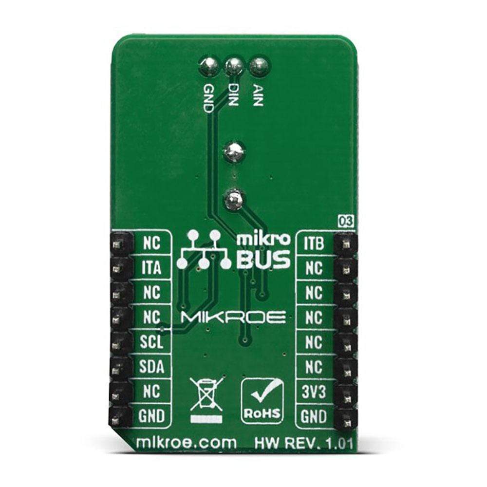
This table shows how the pinout on the RTC 7 Click Board™ corresponds to the pinout on the mikroBUS™ socket (the latter shown in the two middle columns).
| Notes | Pin | Pin | Notes | ||||
|---|---|---|---|---|---|---|---|
| Interrupt B OUT | ITB | 1 | AN | PWM | 16 | NC | |
| NC | 2 | RST | INT | 15 | ITA | Interrupt A OUT | |
| NC | 3 | CS | RX | 14 | NC | ||
| NC | 4 | SCK | TX | 13 | NC | ||
| NC | 5 | MISO | SCL | 12 | SCL | I2C Clock | |
| NC | 6 | MOSI | SDA | 11 | SDA | I2C Data | |
| Power Supply | 3.3V | 7 | 3.3V | 5V | 10 | NC | |
| Ground | GND | 8 | GND | GND | 9 | GND | Ground |
ONBOARD SETTINGS AND INDICATORS
| Label | Name | Default | Description |
|---|---|---|---|
| PWR | PWR | - | Power LED Indicator |
| General Information | |
|---|---|
Part Number (SKU) |
MIKROE-2976
|
Manufacturer |
|
| Physical and Mechanical | |
Weight |
0.02 kg
|
| Other | |
EAN |
8606018716661
|
Frequently Asked Questions
Have a Question?
Be the first to ask a question about this.