Overview
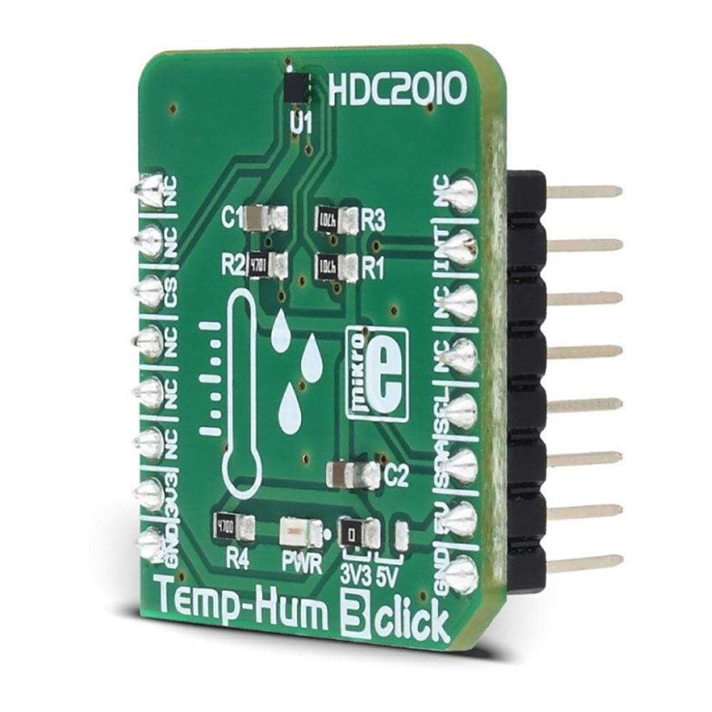
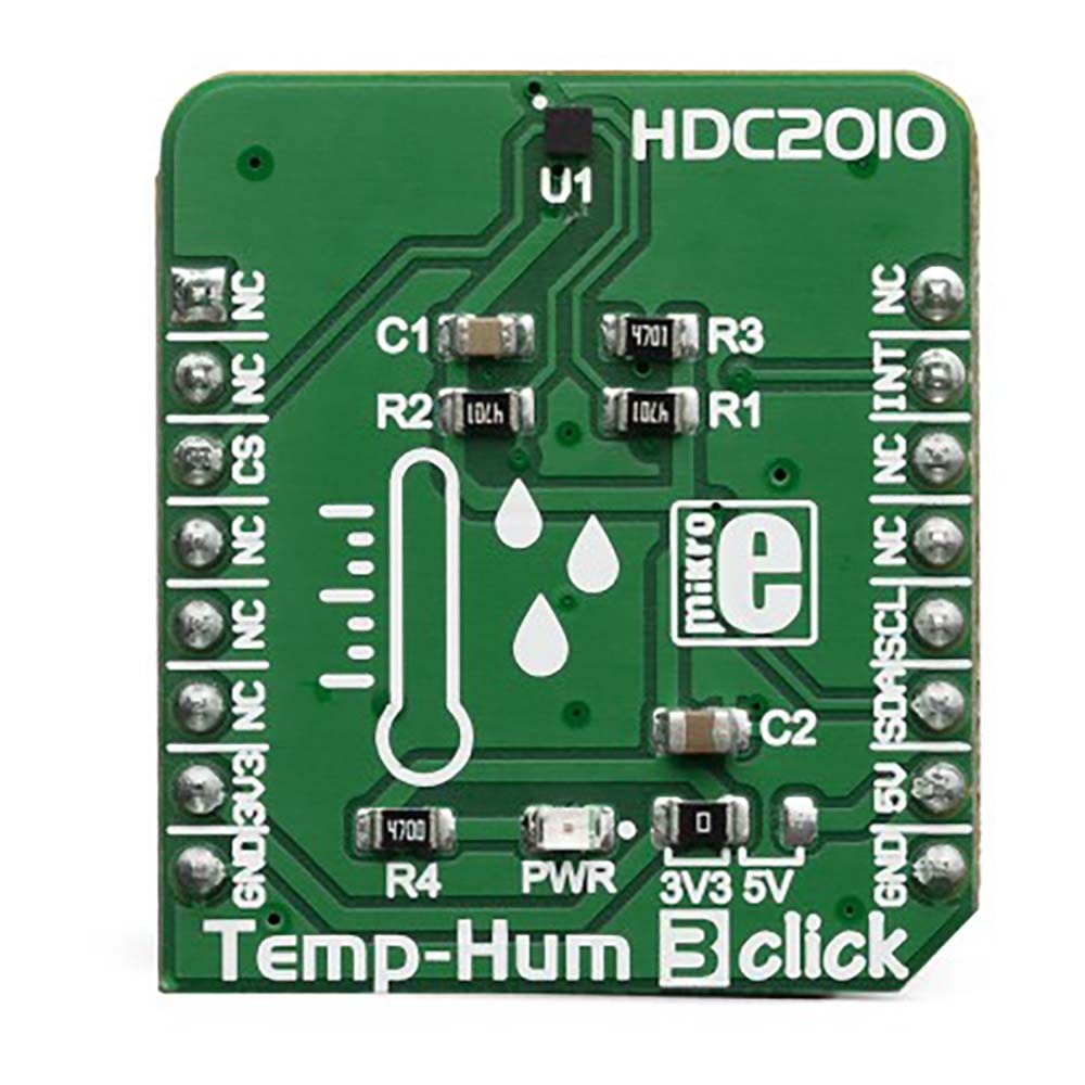
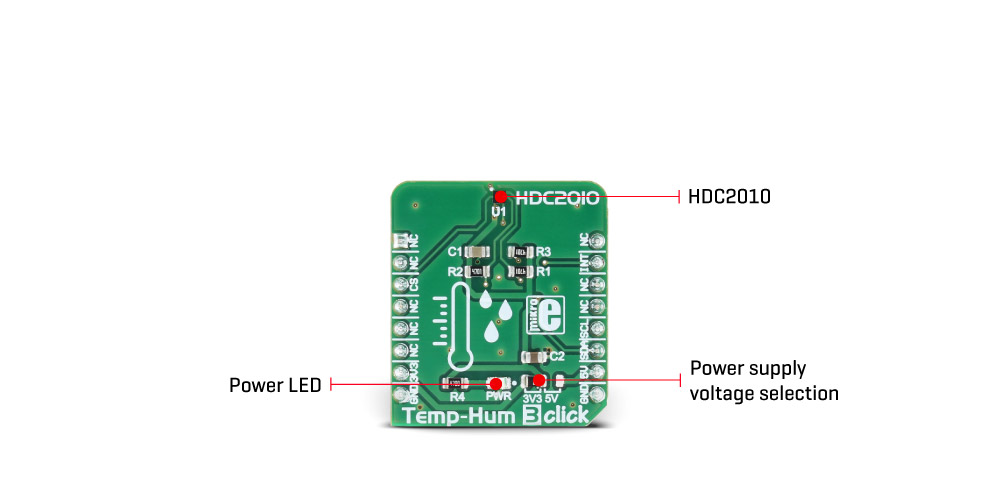
The Temp-Hum 3 Click Board™ is a smart environmental temperature and humidity sensor Click Board™, packed with features which allow easy and simple integration into any design that requires accurate and reliable humidity and temperature measurements. The sensor IC has integrated sensing elements placed on the bottom of the die, so they are not directly exposed to the environmental contamination. This translates to a prolonged life of the Click Board™ itself.
Downloads
The Temp&Hum 3 Click Board™ is a smart environmental temperature and humidity sensor Click board™, packed with features which allow easy and simple integration into any design that requires accurate and reliable humidity and temperature measurements. The sensor IC has integrated sensing elements placed on the bottom of the die, so they are not directly exposed to the environmental contamination. This translates to a prolonged life of the Click board™ itself.
The Temp&Hum 3 Click Board™ is a perfect solution for a wide range of applications that depend on accurate temperature and humidity readings. With its low power consumption and programmable interrupt requests capability, it is also a perfect choice for various temperature and relative humidity based IoT applications, such as smart home applications, smart thermostats, gas sensing, smoke and heat sensors, and similar.
How Does The Temp&Hum 3 Click Board™ Work?
The sensor IC used on the Temp&Hum 3 Click Board™ is the HDC2010, a Low Power Humidity and Temperature Digital Sensor from Texas Instruments. This sensor is factory calibrated to 2% relative humidity and 0.2°C temperature accuracy. It has an integrated heating element that is used to evaporate condensation, protecting the sensor that way. This heating element can be simply activated by setting a bit in the appropriate register. In the case when the heater is powered on, the power consumption might rise to about 130mA.
Internally, two sensors are connected to the ADC section, which can be set to sample measurements with the resolution of 9, 11 or 14 bits, based on the measurement time. The OTP memory holds the calibration coefficients that are applied to the measured value and the results are stored on the output registers, in the MSB/LSB format. These values are then used in formulas found in the HDC2010 datasheet so that the final temperature or relative humidity data can be calculated. It is also possible to correct the offsets with custom values.
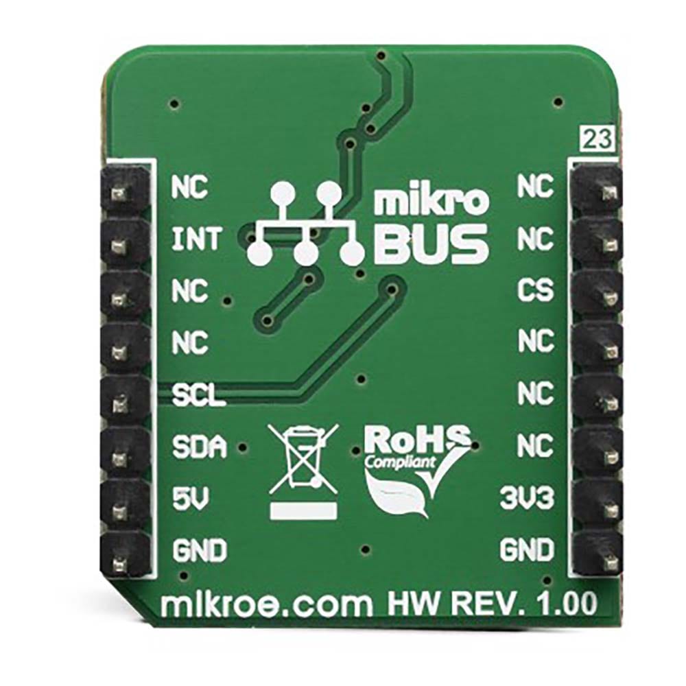
HDC2010 IC uses the I2C protocol to communicate with the host MCU. Its I2C bus pins are routed to the mikroBUS™ I2C pins and are pulled to a HIGH logic level by the onboard resistors. The ADDR pin of the HDC2010 is routed to the CS pin of the mikroBUS™ and it represents the least significant bit of the I2C address. The final I2C address of this IC is determined by setting this pin either to a HIGH logic level for 1, or a LOW logic level for 0.
The Temp&Hum 3 Click Board™ supports programmable interrupt engine, saving the host MCU from having to constantly poll the IC for data. An interrupt signal with a selectable polarity and behavior can be generated on the DRDY/INT pin of the HDC2010. It can be triggered by several event sources: it can be triggered by the temperature Lo/Hi threshold events, Humidity Lo/Hi events, as well as the readiness status of the measurement data. Setting up the interrupts can be achieved by programming the appropriate IC registers via the I2C bus. More information about these registers can be found in the HDC2010 datasheet.
HDC2010 IC itself is a very low power consuming device and it can work in two modes: sleep and active (measurement) mode. The device enters the sleep the mode as soon possible, to save power. While in the active mode, measurement can be either automatic with predefined output data rate (ODR) or on-demand. In the automatic mode, the measurement is triggered in predefined time segments, while on-demand measurement happens whenever the I2C command is sent. As soon as the single measurement is finished, the device falls back to a sleep mode.
Onboard SMD jumper is used to select the power supply voltage. This allows Temp&Hum 3 click to be used with both 3.3V and 5V MCUs.
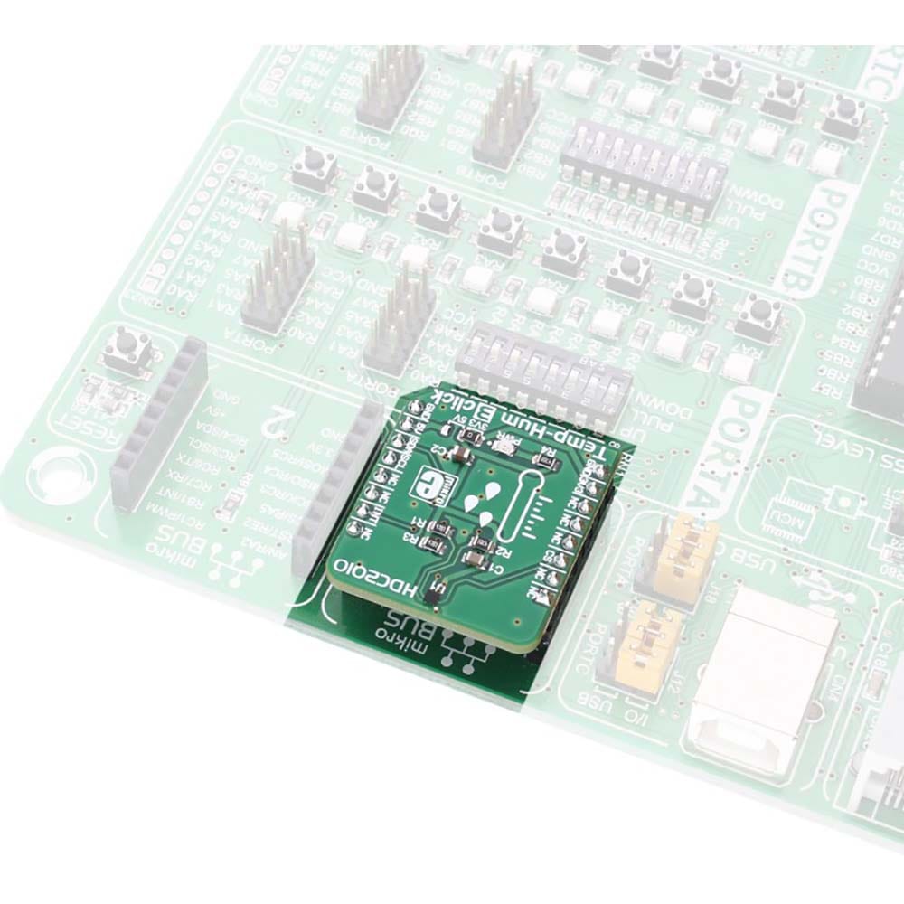
The Temp&Hum 3 Click Board™ library contains simple and easy to use functions, which simplify configuring and reading of the measurement data. These functions are demonstrated in the included example application and can be used as a reference for custom projects. These functions can be used in mikroC, mikroBASIC and mikroPASCAL compilers for all MCU architectures, supported by MikroElektronika.
SPECIFICATIONS
| Type | Temperature & humidity |
| Applications | Environmental monitoring, home automation, weather stations, HVAC systems, wearables, various IoT applications, etc. |
| On-board modules | HDC2010 Low Power Humidity and Temperature Digital Sensor |
| Key Features | The Temp&Hum 3 Click Board™ measures the relative humidity range from 0% to 100%, it has humidity accuracy of ±2%, and it features an integrated heating element, used to evaporate condensation, smart sensor IC design, and low power consumption. |
| Interface | I2C |
| Compatibility | mikroBUS |
| Click board size | S (28.6 x 25.4 mm) |
| Input Voltage | 3.3V or 5V |
PINOUT DIAGRAM
This table shows how the pinout of the Temp&Hum 3 Click Board™ corresponds to the pinout on the mikroBUS™ socket (the latter shown in the two middle columns).
| Notes | Pin |  |
Pin | Notes | |||
|---|---|---|---|---|---|---|---|
| NC | 1 | AN | PWM | 16 | NC | ||
| NC | 2 | RST | INT | 15 | INT | Interrupt output | |
| I2C Address LSB | CS | 3 | CS | RX | 14 | NC | |
| NC | 4 | SCK | TX | 13 | NC | ||
| NC | 5 | MISO | SCL | 12 | SCL | I2C Clock | |
| NC | 6 | MOSI | SDA | 11 | SDA | I2C Data | |
| Power Supply | +3V3 | 7 | 3.3V | 5V | 10 | +5V | Power Supply |
| Ground | GND | 8 | GND | GND | 9 | GND | Ground |
TEMP&HUM 3 CLICK MAXIMUM RATINGS
| Description | Min | Typ | Max | Unit |
|---|---|---|---|---|
| Temperature Accuracy | -0.2 | - | 2 | °C |
| Humidity Accuracy | -2 | - | 2 | % RH |
| Operating temperature | -40 | - | 85 | °C |
| Relative Humidity Operating Range | 0 | - | 100 | % RH |
| I2C clock frequency | 10 | - | 400 | kHz |
ONBOARD SETTINGS AND INDICATORS
| Label | Name | Default | Description |
|---|---|---|---|
| JP1 | - | Left | Power Supply Voltage Selection: Left position 3V3, right position 5V |
| LD1 | PWR | PWR indication LED |
| General Information | |
|---|---|
Part Number (SKU) |
MIKROE-2937
|
Manufacturer |
|
| Physical and Mechanical | |
Weight |
0.019 kg
|
| Other | |
Country of Origin |
|
HS Code Customs Tariff code
|
|
EAN |
8606018712564
|
Warranty |
|
Frequently Asked Questions
Have a Question?
Be the first to ask a question about this.


