

ZeroPlus Technology Co Ltd
Zeroplus Protocol Simulator Board B - 60 Protocol Test Generator
Zeroplus Protocol Simulator Board B - 60 Protocol Test Generator
SKU: PROT-SIM-B
Couldn't load pickup availability

Key Features
Overview
Downloads
Why Engineers Choose The Zeroplus Protocol Simulator Board B - 60 Protocol Test Generator
Protocol Validation
Development Efficiency
Educational Training
Professional Protocol Simulation for Logic Analyser Testing
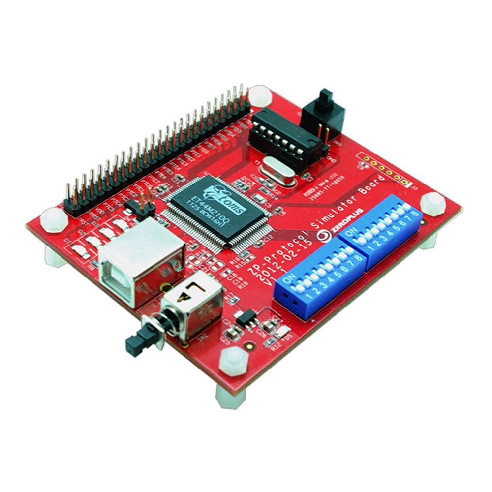
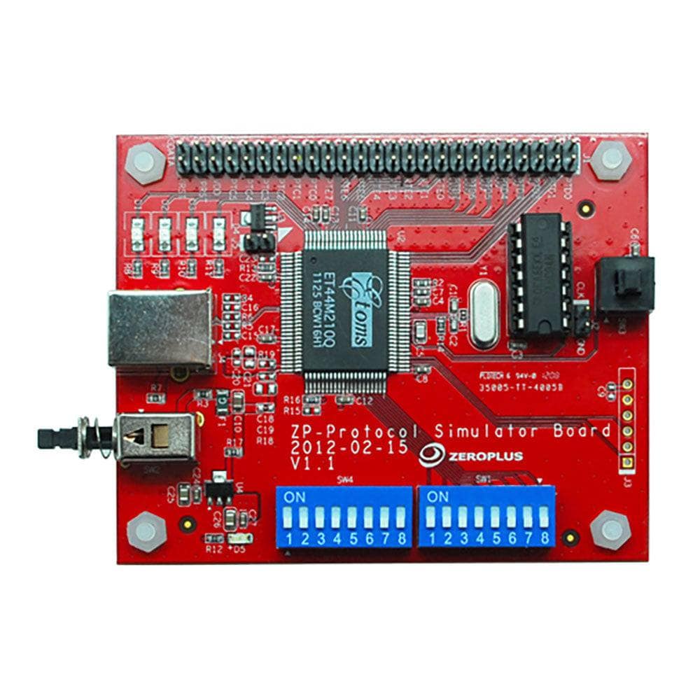
The Zeroplus Protocol Simulator Board B serves as a comprehensive test signal generator designed specifically for logic analyser validation and embedded system debugging. This compact PCB generates authentic protocol data packets across nearly 100 different communication standards, enabling engineers to test and validate their logic analyser setups without requiring live system connections.
Complete Supported Protocol List
The Protocol Simulator Board B supports an extensive range of communication protocols covering embedded systems, industrial automation, memory interfaces, and specialised applications:
| Protocol Category | Supported Protocols | Application Area |
|---|---|---|
| Serial Communication | I2C (EEPROM 24L, 24LCS61/62), UART, SPI (EEPROM AT25F), MODIFIED SPI | Embedded systems, sensor interfaces |
| MICROWIRE (EEPROM 93C), UNI/O, SCCB, 1-Wire, S2CWIRE/AS2CWIRE | Memory devices, temperature sensors | |
| SWD (Serial Wire Debug), SWP, BDM (Background Debug Mode) | Microcontroller debugging | |
| Industrial & Automotive | CAN, LIN, PROFIBUS, HART, BMS (Battery Management) | Automotive, process control |
| MIL-STD-1553, MVB (Multifunction Vehicle Bus), WTB | Aerospace, railway systems | |
| Memory Interfaces | SAMSUNG K9 (NAND Flash), Compact Flash 4.1, eMMC, SD3.0 | Storage devices, embedded memory |
| FWH (Firmware Hub), DS1302 (Real-time clock), DS18B20 | BIOS, timekeeping, temperature sensing | |
| Consumer Electronics | USB 2.0, HDMI_CEC, HD Audio, MIDI | USB devices, multimedia, audio |
| PHILIPS RC-5, PHILIPS RC-6, WIEGAND, DALI Interface | Remote controls, access control, lighting | |
| RF & Wireless | KNX (Building automation), KEELOQ Code Hopping | Home automation, security systems |
| WWV/WWVH/WWVB (Time signals), YK-5 | Time synchronisation, specialised RF | |
| Display & Interface | DSI BUS (Display Serial Interface), LPT (Parallel port) | Display controllers, legacy interfaces |
| HPI (Host Port Interface), CMOS IMAGE, LG4572 | Image sensors, display panels | |
| Encoding & Modulation | MODIFIED MILLER, Differential Manchester, Line Code | Data encoding, communication protocols |
| PT2262/PT2272, SHT11, OPENTHERM2.2 | Remote control, humidity sensors, heating | |
| Test & Measurement | GPIB (IEEE 488), SDQ, SVID, DM114/DM115 | Instrumentation, voltage regulation |
| Advanced Protocols | Quad SPI, PCI, ISO7816 UART | High-speed memory, smart cards |
Key Operating Modes
The simulator board operates in two distinct modes via DIP switch configuration:
| Mode | Operation | Use Case |
|---|---|---|
| Single Packet | Transmits one data packet determined by digital input | Trigger testing, specific protocol validation |
| Continuous Stream | Continuous packet transmission with identical data | Long-term analysis, protocol decoder testing |
Protocol Selection and Control
Protocol selection utilises a dedicated DIP switch array allowing instant switching between supported communication standards. The board features convenient test points and standard logic analyser probe compatibility for seamless integration into existing test setups.
Physical Specifications
Measuring 7.0cm (W) × 9.7cm (D) × 2.5cm (H), the board maintains a compact footprint suitable for benchtop testing environments. The PCB includes multiple ground connections and signal routing optimised for minimal noise and crosstalk during protocol generation.
// Example connection setup Logic Analyser CH0-7 → Protocol Output Pins Ground References → Board GND pins Power Supply → 5V DC input Protocol Select → DIP switch array Applications in Development
Essential for embedded system validation, the simulator board enables testing of communication protocols before deploying to live systems. Engineers use it for protocol decoder validation, timing analysis verification, and logic analyser trigger configuration testing.
| General Information | |
|---|---|
Part Number (SKU) |
PROT-SIM-B
|
Manufacturer |
|
| Physical and Mechanical | |
Weight |
0.5 kg
|
| Other | |
EAN |
5055383620500
|
Frequently Asked Questions
Have a Question?
-
Are any additional protocols supported beyond the Protocol Simulator Board B?
Yes, Zeroplus offers the Protocol Simulator Board Awhich supports a different set of nearly 100 protocols. Board A includes protocols such as 1-WIRE, 3-WIRE, 7-SEGMENT LED, AC97, ARITHMETICAL LOGIC, CCIR656, DIGITAL LOGIC, DMX512, DSA Interface, FlexRay2.1A, HDQ, IRDA, I2C, I2S, JK FLIP-FLOP, JTAG2.0, LCD12864, LPC-SERIRQ, LCD1602, LIN 2.1, Low Pin Count, MCU-51 DECODE, ModBus, MANCHESTER, MICROWIRE, MII, MILLER, NEC PD6122, PCM, PECI, PM BUS1.1, PSB Interface, PS/2, SLE4442, SM BUS2.0, ST7669, ST BUS, SD2.0/SDIO, S/PDIF, SPI, SSI Interface, UART(RS-232C/422/485), UP COUNTER, USB1.1, CAN 2.0B, and DIGRF. The two boards complement each other, providing coverage across different protocol families and applications. Both boards share the same physical dimensions (7×9.7×2.5cm) and operating principles but target different protocol sets for comprehensive testing coverage.
-
How does this compare to software-based protocol simulators?
Hardware simulators like the Protocol Simulator Board B provide authentic electrical timing and signal characteristics that software simulators cannot replicate. This includes proper rise/fall times, impedance matching, and real-world signal integrity aspects crucial for comprehensive logic analyser testing and validation.
-
Can I modify packet content in the continuous stream mode?
The continuous stream mode transmits pre-configured packet patterns specific to each protocol. Packet content modification typically requires single packet mode where digital inputs determine the data content. Some protocols may offer limited content variation through DIP switch sub-settings.
-
What documentation comes with the Protocol Simulator Board B?
The board includes a comprehensive user guide detailing supported protocols, DIP switch settings, connection diagrams, and example configurations. Additional resources include protocol timing diagrams and sample logic analyser capture examples.
-
Is this suitable for educational use and training?
Absolutely. The Protocol Simulator Board B serves as an excellent educational tool for teaching digital communication protocols and logic analyser usage. It provides students with consistent, repeatable protocol signals for learning analysis techniques without complex hardware requirements.
-
How do I connect the simulator board to my logic analyser?
Connect the protocol output pins to your logic analyser's input channels using standard probe leads or flying leads. Ensure proper ground connections between the board and logic analyser. The board provides clearly marked test points for easy probe attachment.
-
What are the power supply requirements of the board?
The Protocol Simulator Board B typically requires 5V DC power supply. Check the board documentation for specific current requirements and connector types. Most setups can power the board from the logic analyser's auxiliary power output or a standard bench power supply.
-
What's the difference between single packet and continuous stream modes?
Single packet mode transmits one data packet when triggered, with packet content determined by digital inputs to the board. Continuous stream mode repeatedly transmits identical packets continuously. Single mode suits trigger testing whilst continuous mode benefits long-term protocol analysis and decoder validation.
-
Can this simulator board work with non-Zeroplus logic analysers?
Yes, the Protocol Simulator Board B outputs standard TTL/CMOS logic levels compatible with most logic analysers including Saleae, Acute Technology, and other manufacturers' devices. Ensure your logic analyser supports the appropriate voltage thresholds and sampling rates.
-
How do I select different protocols on the simulator board?
Protocol selection uses a DIP switch array located on the board. Each switch position corresponds to a specific protocol. Simply set the switches to the desired protocol code (referenced in the included documentation) and power cycle the board to activate the selected protocol.
-
What protocols does the Protocol Simulator Board B support?
The board supports 60 different communication protocols including I2C, SPI, UART, CAN, USB, Ethernet, and numerous industrial and embedded system standards. The complete protocol list varies by firmware version but covers the most commonly used digital communication methods in embedded systems.