


Mikroelektronika d.o.o.
Stepper 2 Click Board™
Stepper 2 Click Board™
SKU: MIKROE-1926
Couldn't load pickup availability
Overview
An improvement over its predecessor, the Stepper 2 Click Board™ from MikroE is another addition in the range of motor driver Click Boards™. Complete with an A4988 microstepping motor driver, the Stepper 2 Click Board™ surpasses the original Stepper Click Board™ with an output drive capability of up to 35V and 2A.
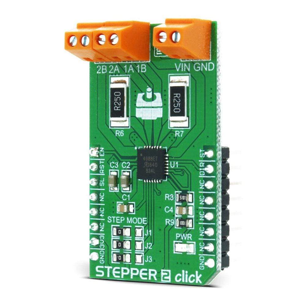
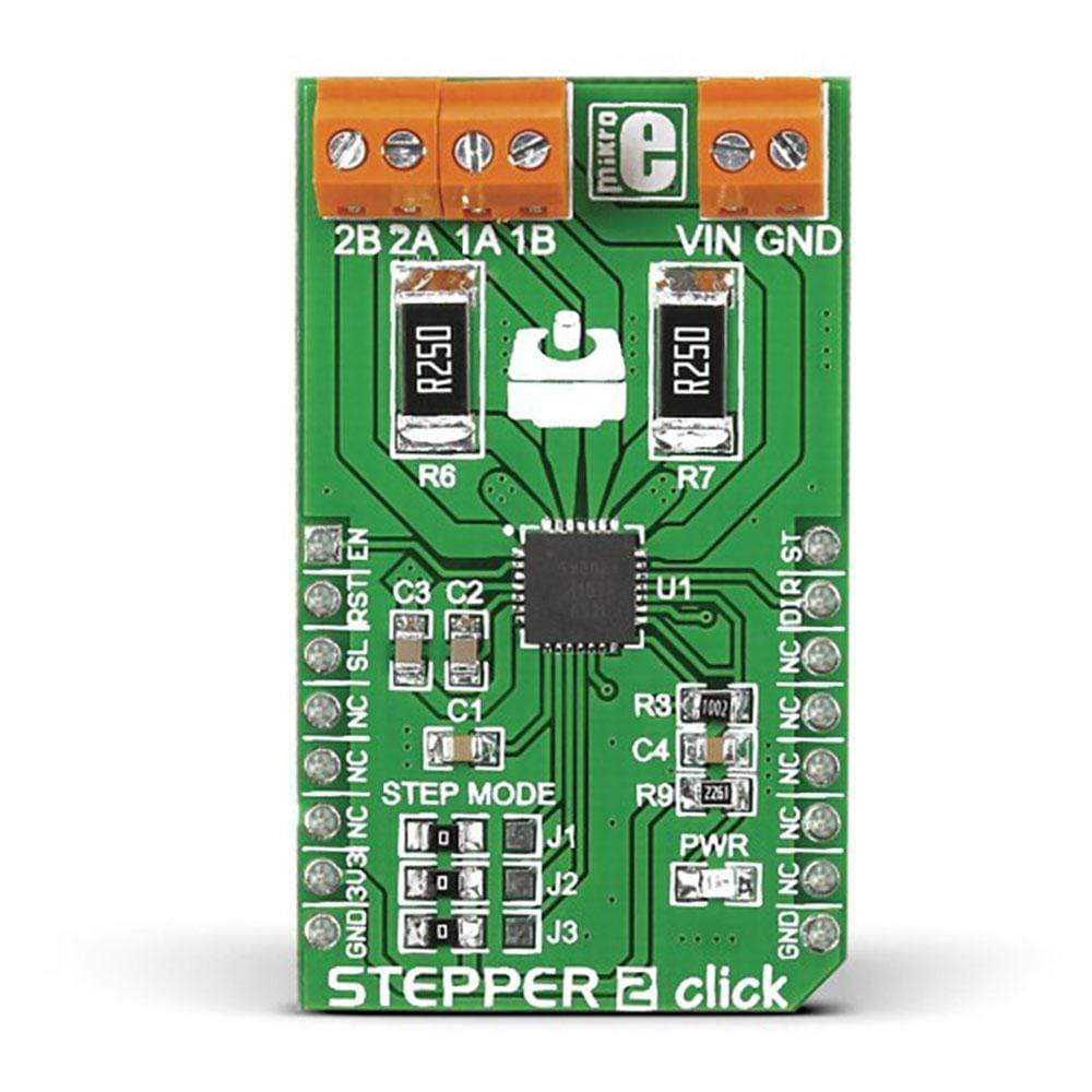
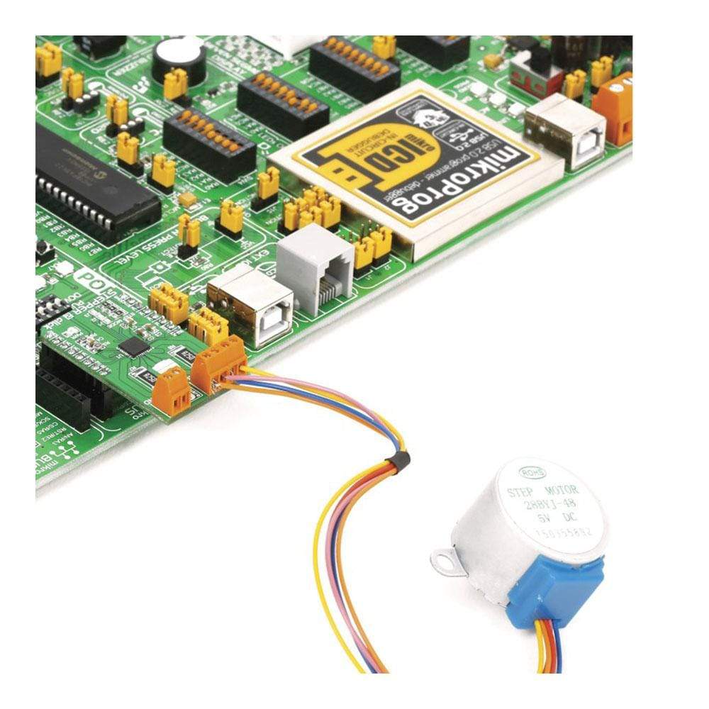
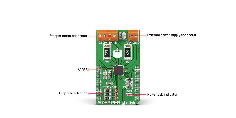
Not just power, the new version is designed to offer users more control (precision). It can go down to 1/16th of a step to drive the motor. The board features three pairs of onboard screw terminals for secure connectivity. The first two (2B, 2A; 1A, 1B) are for connecting the motor while the third pair (VIN and GND) is for an external power supply (minimum 7V).
The Stepper 2 Click Board™ is intended to operate bipolar stepper motors in full-, half-, quarter-, eighth-, and sixteenth-step modes. The user can select between the different stepping modes (steps and micro-steps) using a set of three (J1-J3) onboard jumpers. Stepper 2 Click Board™ uses MikroBUS EN, RST, SL, ST and DIR pins to communicate with the target board microcontroller. It is designed to work with a 3.3V power supply but is also compatible with a 5V logic level.
Downloads
The Stepper 2 Click Board™ is a complete solution for driving bipolar stepper motors with full/half and micro-steps. It features the A4988 IC from Allegro Microsystems with DMOS low RDS ON drivers on its outputs, which ensure high efficiency and reliable operation of the internal H-Bridges. This IC has the integrated translator section, used to simplify the control: using simple step control inputs from the host MCU, the stepper motor can be driven in both directions, with the predetermined step sizes. In addition, the output current is regulated allowing for noiseless operation of the stepper motor, with no resonance and ringing typically observed at unregulated stepper driver designs.
Additional features of the Stepper 2 Click Board™ include under-voltage, shoot-through, short circuit, overcurrent and thermal protection, so the Click board™ can operate reliably. With its input voltage range up to 35V, it can drive a wide range of stepper motors with up to 2A max. Due to simplicity of the step motor control, as well as the selection of various stepping modes offered by this Click board™, it is a perfect solution for building various applications that require precise and reliable stepper motor control, such as the movement control of beds, heads, and assemblies of various CNC plotting, milling and 3D printer designs.
How Does The Stepper 2 Click Board™ Work?
The Stepper 2 Click Board™ uses the A4988, a micro-stepping driver IC with a translator and overcurrent protection, from Allegro Microsystems. This is a highly integrated IC, which offers a very simple bipolar stepper motor control interface, thanks to the integrated translator section. This section controls the output drivers, providing smooth action of the stepper motor. By controlling the current intensity and its decay throughout the rotation cycle, a constant torque is achieved for every position. The current regulator uses an internal comparator, DA converter (DAC), and external sensing resistor. The current is limited by the sensing resistor to about 1.6A (for a reference voltage of 3.3V). Absolute current limit on this IC is 2.1A, after which the overcurrent protection is activated.
A LOW to HIGH transition on the STEP pin of the A4988 IC will perform one rotational step. The direction of the rotation is controlled by the logic state on the DIR pin (routed to the mikroBUS™ INT pin, labeled as DIR). The step size is determined by three pins: MS1, M2, and MS3. It is possible to work with five-movement step sizes, ranging from full step size up to sixteenth step size. MS1, MS2, and MS3 pins are routed to the SMD jumpers labeled as STEP MODE (J1, J2, and J3), allowing step size to be selected by moving each of them according to the truth table below.
This device supports the Sleep mode, which is activated by a LOW logic level on the SLEEP pin. This will power down the unused sections of the A4988 IC, reducing power consumption to a minimum. After the wake-up event (logic HIGH on the SLEEP pin), at least 1ms of delay is required until the charge pump capacitors are recharged, allowing normal operation of the output stage drivers.
The #ENABLE pin allows the host MCU to enable or disable the output stage MOSFETs of the A4988 IC. Asserting this pin to a LOW logic level enables the output stage. The #RESET pin is used to set DACs and the phase current polarity to the initial Home state. The #ENABLE pin is routed to the AN (labeled as EN), while the #RESET pin is routed to the RST pin of the mikroBUS™, allowing the host MCU to control the IC via these pins.
The Stepper 2 Click Board™ is equipped with the input and output screw terminals. The terminal labeled as CN1 on the schematic is used to connect the external power supply, which should stay in the range from 8V to 35V. The stepper motor can be connected via the CN2 and CN3 screw terminals, with their input terminals labeled as 1A, 1B, and 2A, 2B. The logic section and the reference voltage pin of the IC are powered via the 3.3V mikroBUS™ rail.
MICROSTEP RESOLUTION CONFIGURATION
| Step size: | Full | Half | 1/4 | 1/8 | 1/16 |
|---|---|---|---|---|---|
| MS1 | L | H | L | H | H |
| MS2 | L | L | H | H | H |
| MS3 | L | L | L | L | H |
SPECIFICATIONS
| Type | Stepper |
| Applications | The Stepper 2 Click Board™ is a perfect solution for building various applications that require a precise and reliable stepper motor control, such as the movement control of beds, heads, and assemblies of various CNC plotting, milling, and 3D printer designs. |
| On-board modules | A4988, a micro-stepping driver IC with a translator, from Allegro Microsystems, LLC. |
| Key Features | Integrated translation section used to simplify the control, ability to run in full, half, quarter, eighth and sixteenth step, undervoltage, overcurrent and thermal protection, etc. |
| Interface | GPIO |
| Compatibility | mikroBUS |
| Click board size | M (42.9 x 25.4 mm) |
| Input Voltage | 3.3V |
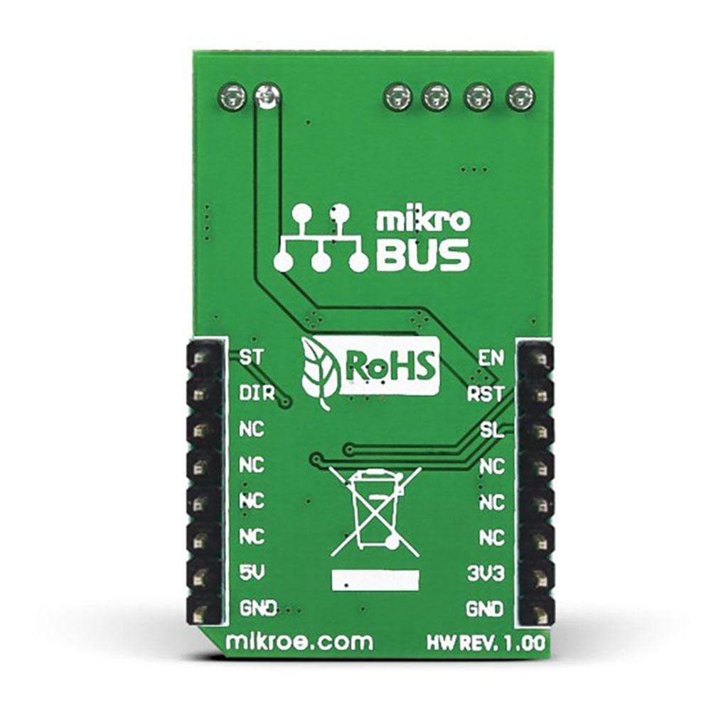
PINOUT DIAGRAM
This table shows how the pinout on the Stepper 2 Click Board™ corresponds to the pinout on the mikroBUS™ socket (the latter shown in the two middle columns).
| Notes | Pin | Pin | Notes | ||||
|---|---|---|---|---|---|---|---|
| Chip Enable | EN | 1 | AN | PWM | 16 | ST | Step trigger |
| Reset | RST | 2 | RST | INT | 15 | DIR | Direction |
| Sleep | SL | 3 | CS | RX | 14 | NC | |
| NC | 4 | SCK | TX | 13 | NC | ||
| NC | 5 | MISO | SCL | 12 | NC | ||
| NC | 6 | MOSI | SDA | 11 | NC | ||
| Power supply | +3.3V | 7 | 3.3V | 5V | 10 | NC | |
| Ground | GND | 8 | GND | GND | 9 | GND | Ground |
STEPPER 2 CLICK ELECTRICAL SPECIFICATIONS
| Description | Min | Typ | Max | Unit |
|---|---|---|---|---|
| External power supply voltage | 8 | - | 35 | V |
| Current limit | - | - | 1.6 | A |
| Step size | 1 | - | 1/16 | step |
ONBOARD SETTINGS AND INDICATORS
| Label | Name | Default | Description |
|---|---|---|---|
| PWR | PWR | - | Power LED indicator |
| J1-J3 | STEP MODE | Left | Step size selection: left position L, right position H (settings in the truth table) |
| CN1 | VIN | - | External power supply connector |
| CN2 | 2A,2B | - | Stepper motor coil 2 connector |
| CN3 | 1A,1B | - | Stepper motor coil 1 connector |
| General Information | |
|---|---|
Part Number (SKU) |
MIKROE-1926
|
Manufacturer |
|
| Physical and Mechanical | |
Weight |
0.028 kg
|
| Other | |
EAN |
8606015076997
|
Frequently Asked Questions
Have a Question?
Be the first to ask a question about this.