


Mikroelektronika d.o.o.
Relay 5 Click Board
Relay 5 Click Board
Couldn't load pickup availability
Key Features:
- Three electro-mechanical relays, low power consumption, reliable switching, high current, high sensitivity, SPDT configuration, relay activity indicators, long mechanical life, control over the I/O port expander, and more
- Based on the J1031C3VDC.15S - high-current single-pole double-throw (SPDT) signal relays from CIT Relay and Switch PCA9538A - low-voltage 8-bit I/O port expander from NXP Semiconductors
- Can be used for controlling high-power applications
- mikroBUS: I2C Interface
The Relay 5 Click Board™: Control High-Power Applications with Ease
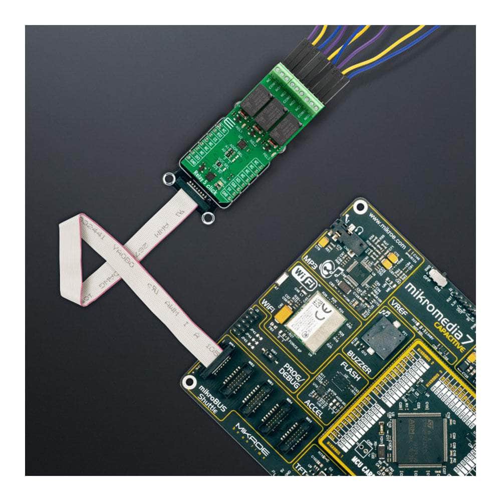
The Relay 5 Click Board™ is a compact add-on board designed for easy control of general-purpose I2C-controlled relays by any host MCU. With its versatile features and reliable performance, this board is a must-have for your projects.
Powerful and Efficient
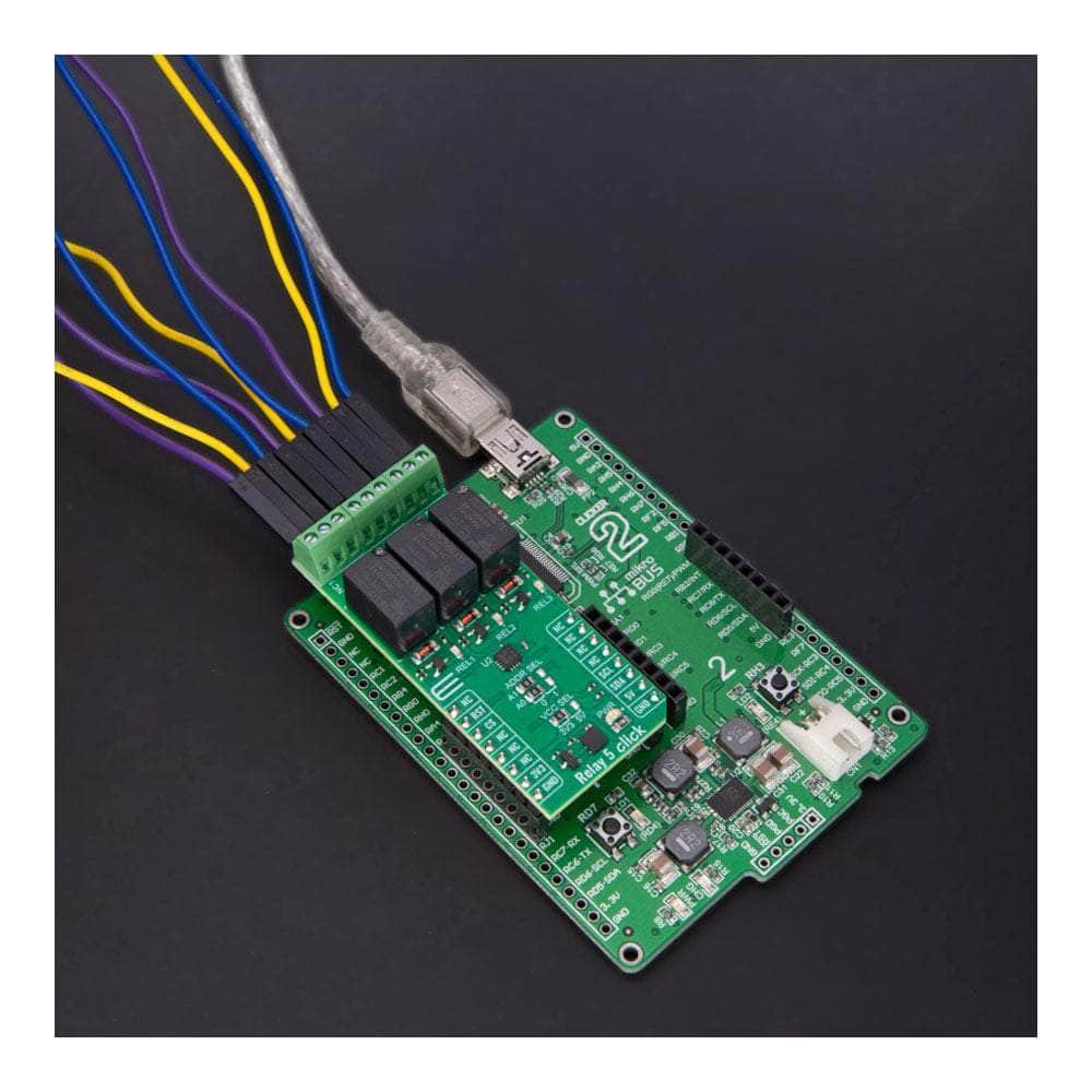
This board ensures precise and efficient relay operations by featuring three J1031C3VDC.15S high-current single-pole double-throw (SPDT) signal relays controlled by the PCA9538A. The J1031C3VDC.15S relays are highly sensitive, providing low coil power consumption while maintaining a small and lightweight form factor with PC pin mounting.
Compact and Versatile
With dimensions of 12.5x7.5x10 millimetres (LxWxH), the Relay 5 Click Board™ offers a compact solution for your projects without compromising performance. It features a 1C contact arrangement and a coil voltage of 3VDC, enabling a maximum switching voltage of 125VAC/60VDC. This board is designed to handle high-power applications with ease.
Simplified Software Development
The Relay 5 Click Board™ is supported by a mikroSDK-compliant library, providing you with a seamless software development experience. The included functions make integrating this Click board™ into your existing projects easy, saving you valuable time and effort.
Ready-to-Use Solution
When you choose the Relay 5 Click Board™, you can rest assured that you're getting a fully tested and reliable product. It comes ready to be used with any system equipped with the mikroBUS™ socket, allowing for quick and hassle-free integration into your projects.
Take control of high-power applications effortlessly with the Relay 5 Click Board™. Get yours today and experience the convenience and reliability it brings to your projects!
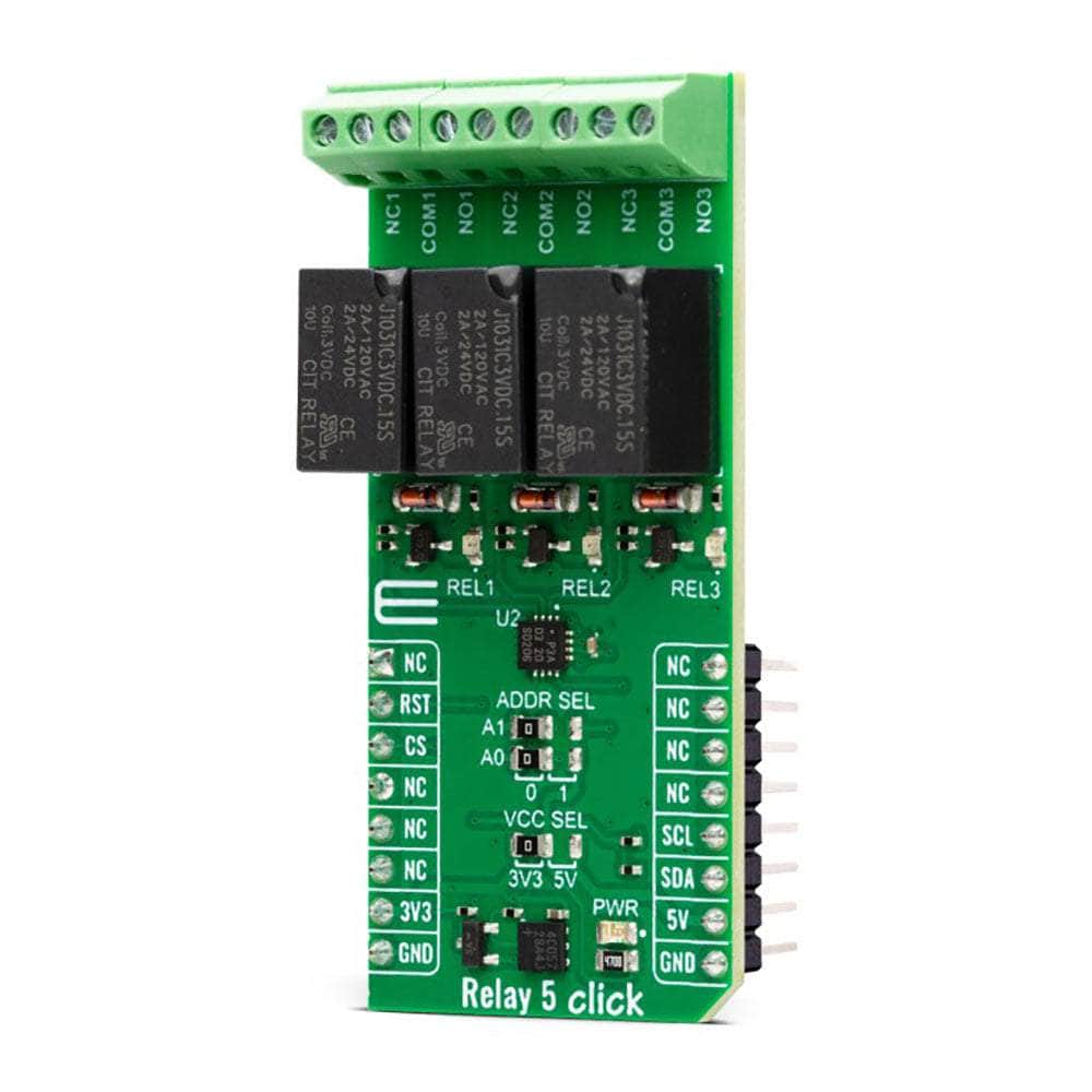

How Does The Relay 5 Click Board™ Work?
The Relay 5 Click Board™ is based on three J1031C3VDC.15S, a high-current single-pole double-throw (SPDT) signal relays from CIT Relay and Switch, controlled in a very simple way through a port expander from NXP Semiconductors, the PCA9538A. The J1031C3VDC.15S relay is well known for its reliability and durability, high sensitivity, and low coil power consumption housed in a small package with PC pin mounting. Despite its size (12.5x7.5x10 millimeters (LxWxH)), the J1031C3VDC relay can withstand up to 2A and 125VAC/60VDC maximum. These relays are designed to easily activate their coils by relatively low currents and voltages, making them a perfect choice that any MCU can control. Besides, their durability is impressive, with over 5M of mechanical life cycles.
.jpg)
The contact configuration of the J1031C3VDC.15S is a single-pole double-throw (SPDT), meaning it has one pole and two throws. Based on the default position of the pole, one throw is considered normally open (NO) while the other is normally closed (NC), which is, in this case, its default position. When the coil is energized, it will attract the internal switching elements similar to a switch. For this purpose, the Relay 5 Click has three terminals for each relay that are adequately labelled. In addition, every relay has its status LED (REL1-3) for visual status presentation.
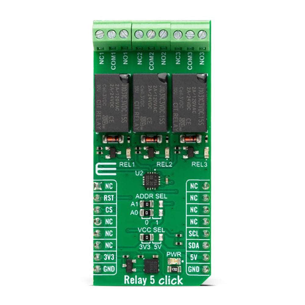
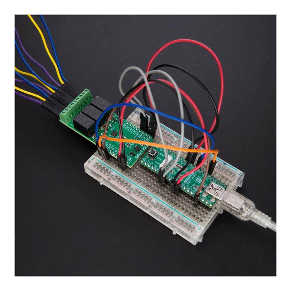
As mentioned, the relays are not directly driven by the host MCU but by the PCA9538A, a low-voltage 8-bit I/O port with interrupt and reset from NXP Semiconductors. This I/O expander provides a simple solution when additional I/Os are needed while keeping interconnections to a minimum. The Relay 5 Click uses the PCA9538A and 2-Wire I2C interface to communicate with the host MCU. The PCA9538A supports a fast mode of up to 400KHz of clock frequency. The I2C Address can be selected via the ADDR SEL jumpers, with 0 selected by default. The expander can be reset over the RST pin with active LOW, thus setting the registers to their default values without the need to power it off.
The Relay 5 Click Board™ can operate with either 3.3V or 5V logic voltage levels selected via the VCC SEL jumper. This way, both 3.3V and 5V capable MCUs can use the communication lines properly. However, the Click board™ comes equipped with a library containing easy-to-use functions and an example code that can be used, as a reference, for further development.
SPECIFICATIONS
| Type | Relay |
| Applications | Can be used for controlling high-power applications |
| On-board modules | J1031C3VDC.15S - high-current single-pole double-throw (SPDT) signal relays from CIT Relay and Switch PCA9538A - low-voltage 8-bit I/O port expander from NXP Semiconductors |
| Key Features | Three electro-mechanical relays, low power consumption, reliable switching, high current, high sensitivity, SPDT configuration, relay activity indicators, long mechanical life, control over the I/O port expander, and more |
| Interface | I2C |
| Compatibility | mikroBUS |
| Click board size | L (57.15 x 25.4 mm) |
| Input Voltage | 3.3V or 5V |
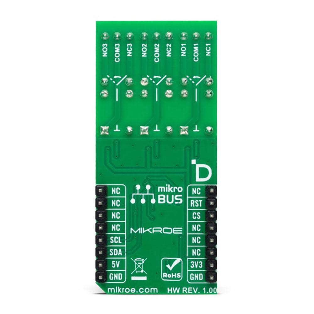
PINOUT DIAGRAM
This table shows how the pinout of the Relay 5 Click Board™ corresponds to the pinout on the mikroBUS™ socket (the latter shown in the two middle columns).
| Notes | Pin | Pin | Notes | ||||
|---|---|---|---|---|---|---|---|
| NC | 1 | AN | PWM | 16 | NC | ||
| Reset | RST | 2 | RST | INT | 15 | NC | |
| NC | 3 | CS | RX | 14 | NC | ||
| NC | 4 | SCK | TX | 13 | NC | ||
| NC | 5 | MISO | SCL | 12 | SCL | I2C Clock | |
| NC | 6 | MOSI | SDA | 11 | SDA | I2C Dlock | |
| Power Supply | 3.3V | 7 | 3.3V | 5V | 10 | 5V | Power Supply |
| Ground | GND | 8 | GND | GND | 9 | GND | Ground |
ONBOARD SETTINGS AND INDICATORS
| Label | Name | Default | Description |
|---|---|---|---|
| LD1 | PWR | - | Power LED Indicator |
| LD2-LD3 | REL1-REL3 | - | Relay Status LED Indicators |
| JP1 | VCC SEL | Left | Logic Voltage Level Selection 3V3/5V: Left position 3V3, Right position 5V |
| JP2 | ADDR SEL | Right | I2C Address Selection 0/1: Left position 0, Right position 1 |
RELAY 5 CLICK ELECTRICAL SPECIFICATIONS
| Description | Min | Typ | Max | Unit |
|---|---|---|---|---|
| Supply Voltage | 3.3 | - | 5 | V |
| Maximum Switching AC Voltage | - | - | 125 | V |
| Maximum Switching DC Voltage | - | - | 60 | V |
| Maximum Current Switching | - | - | 2 | A |
Software Support
Software Support
We provide a library for the Relay 5 Click Board™ as well as a demo application (example), developed using MIKROE compilers. The demo can run on all the main MIKROE development boards.
The package can be downloaded/installed directly from NECTO Studio The package Manager (recommended), downloaded from our LibStock™ or found on MikroE Github account.
Library Description
This library contains API for the Relay 5 Click Board™ driver.
Key functions
-
relay5_set_relay1_openThis function sets the relay 1 to normally open state by setting the RL1 pin to low logic level. -
relay5_set_relay1_closeThis function sets the relay 1 to normally close state by setting the RL1 pin to high logic level. -
relay5_switch_relay1This function switches the relay 1 state by toggling the RL1 pin logic level.
Example Description
This example demonstrates the use of the Relay 5 Click Board™ by toggling the relays state.
void application_task ( void )
 {
     relay5_set_relay1_open ( &relay5 );
     log_printf( &logger, " Relay 1 set to normally open statern" );
     relay5_set_relay2_close ( &relay5 );
     log_printf( &logger, " Relay 2 set to normally close statern" );
     relay5_set_relay3_open ( &relay5 );
     log_printf( &logger, " Relay 3 set to normally open staternn" );
     Delay_ms ( 5000 );

     relay5_set_relay1_close ( &relay5 );
     log_printf( &logger, " Relay 1 set to normally close statern" );
     relay5_set_relay2_open ( &relay5 );
     log_printf( &logger, " Relay 2 set to normally open statern" );
     relay5_set_relay3_close ( &relay5 );
     log_printf( &logger, " Relay 3 set to normally close staternn" );
     Delay_ms ( 5000 );
 }
The full application code, and ready to use projects can be installed directly from NECTO Studio The package Manager (recommended), downloaded from our LibStock™ or found on MikroE Github account.
Other MikroE Libraries used in the example:
- MikroSDK.Board
- MikroSDK.Log
- Click.Relay5
Additional Notes and Information
Depending on the development board you are using, you may need USB UART Click Board™, USB UART 2 Click or RS232 Click to connect to your PC, for development systems with no UART to USB interface available on the board. UART terminal is available in all MIKROE compilers.
MIKROSDK
The Relay 5 Click Board™ is supported with mikroSDK - MIKROE Software Development Kit, that needs to be downloaded from the LibStock and installed for the compiler you are using to ensure proper operation of mikroSDK compliant Click board™ demo applications.
Relay 5 Click Board
Frequently Asked Questions
Have a Question?
Be the first to ask a question about this.