


Mikroelektronika d.o.o.
ISM Click Board™
ISM Click Board™
SKU: MIKROE-4625
Couldn't load pickup availability


Overview
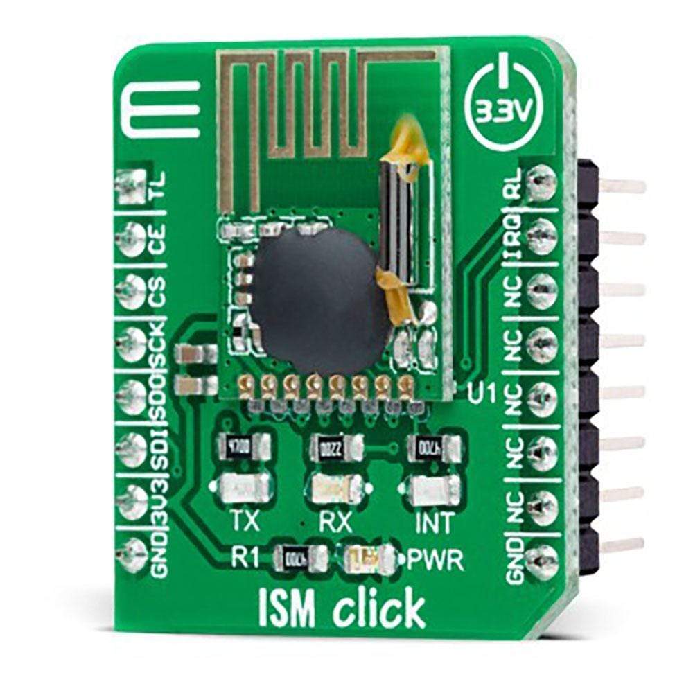
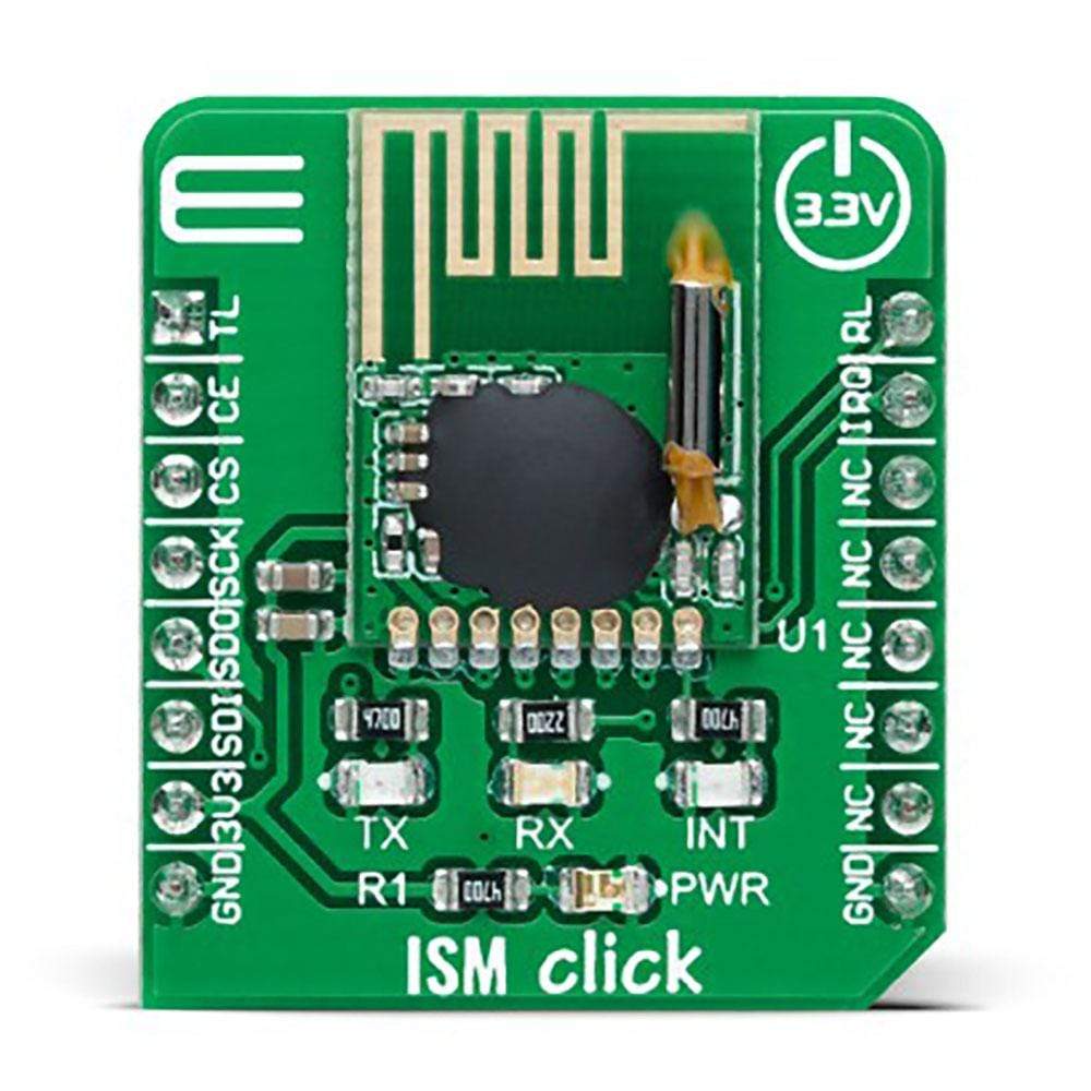
The ISM Click Board™ is a compact add-on board that contains a complete wireless RF digital data transceiver. This board features the RFM75, a low-power, high-performance 2.4GHz GFSK transceiver from RF Solutions. The RFM75 transceiver is configurable through SPI serial interface and operates with only 3.3V in the worldwide ISM frequency band from 2400MHz up to 2527MHz. The embedded packet processing engines enable their entire operation with a simple MCU as a radio system. Burst mode transmission and up to 2Mbps air data rate make it suitable for ultra-low power consumption applications.
This ISM Click Board™ is ideal for home appliances, remote control applications, consumer electronics, and many more.
Downloads
How Does The ISM Click Board™ Work?
The ISM Click Board™ as its foundation uses the RFM75, a low-power, high-performance 2.4GHz GFSK transceiver operating in the worldwide ISM frequency band from 2400MHz up to 2527MHz from RF Solutions. The RFM75 operates in TDD mode, either as a transmitter or as a receiver. Burst mode transmission and up to 2Mbps air data rate make it suitable for applications requiring ultra-low power consumption. The embedded packet processing engines enable their entire operation with a simple MCU as a radio system. Auto re-transmission and auto acknowledge giving reliable link without any MCU interference.
A transmitter and a receiver must be programmed with the same RF channel frequency to communicate with each other supporting a programmable air data rate of 250Kbps, 1Mbps, or 2Mbps. The RF channel frequency determines the center of the channel used by RFM75. The RF_CH register, in register bank 0, sets the frequency according to the following formula F0= 2400 + RF_CH (MHz), where the resolution of the RF channel frequency is 1MHz.
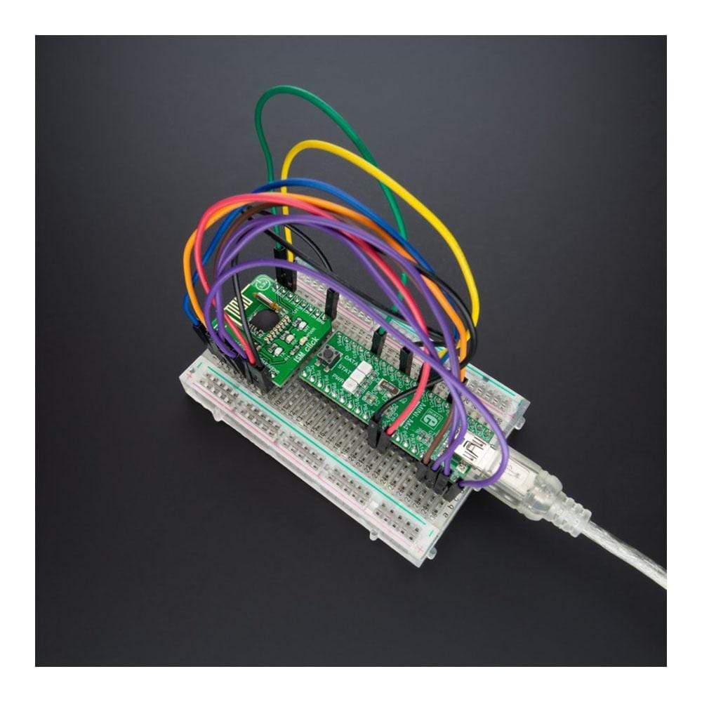
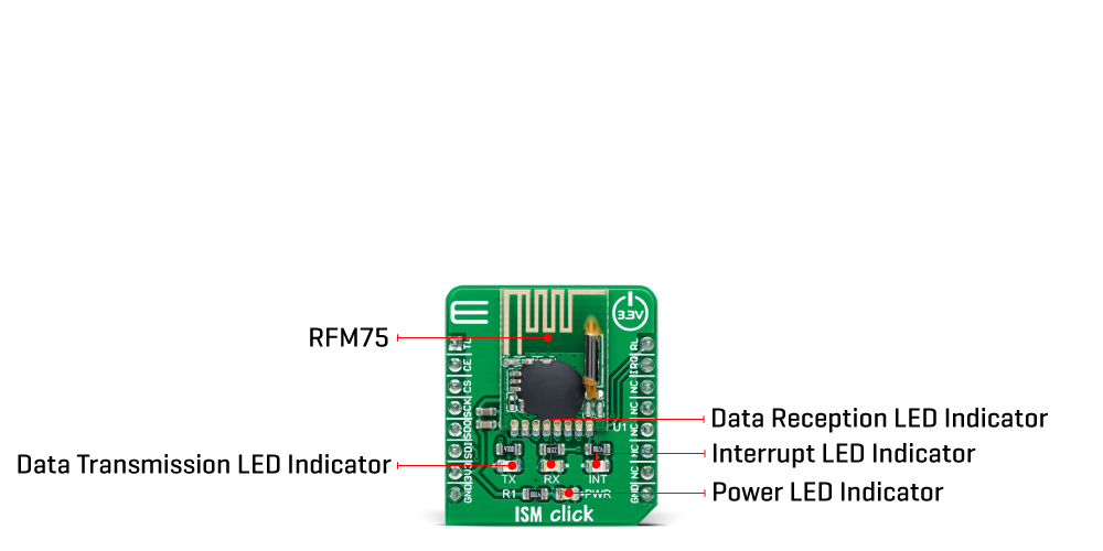
The ISM Click Board™ communicates with MCU using the standard SPI serial interface that operates at clock rates up to 8 MHz. In power-down mode, RFM75 is in Sleep mode with minimal current consumption. SPI interface is still active in this mode, and all register values are available by SPI interface. This Click board™ also has a yellow LED indicator routed on the INT pin of the mikroBUS™ socket (provide the user with feedback after a successfully received package) and chip-enable function routed on the RST pin of the mikroBUS™ which activates TX or RX mode of the RFM75. Besides, it also has two additional LED indicators, a red and blue LED routed on the AN and PWM pins of the mikroBUS™ socket. The user can use it for visual indication when sending or receiving data.
The ISM Click Board™ can be operated only with a 3.3V logic voltage level. The board must perform appropriate logic voltage level conversion before use with MCUs with different logic levels. However, the Click board™ comes equipped with a library containing functions and an example code that can be used, as a reference, for further development.
SPECIFICATIONS
| Type | 2.4 GHz Transceivers |
| Applications | Can be used for home appliances, remote control applications, consumer electronics, and many more. |
| On-board modules | RFM75 - low-power, high-performance 2.4GHz GFSK transceiver operating in the worldwide ISM frequency band from 2400MHz up to 2483.5MHz from RF Solutions |
| Key Features | Low power consumption, 2400-2483.5 MHz ISM band operation, support 250Kbps, 1Mbps and 2 Mbps air data rate, automatic packet processing, high performance, SPI interface, and more. |
| Interface | SPI |
| Compatibility | mikroBUS |
| Click board size | S (28.6 x 25.4 mm) |
| Input Voltage | 3.3V |
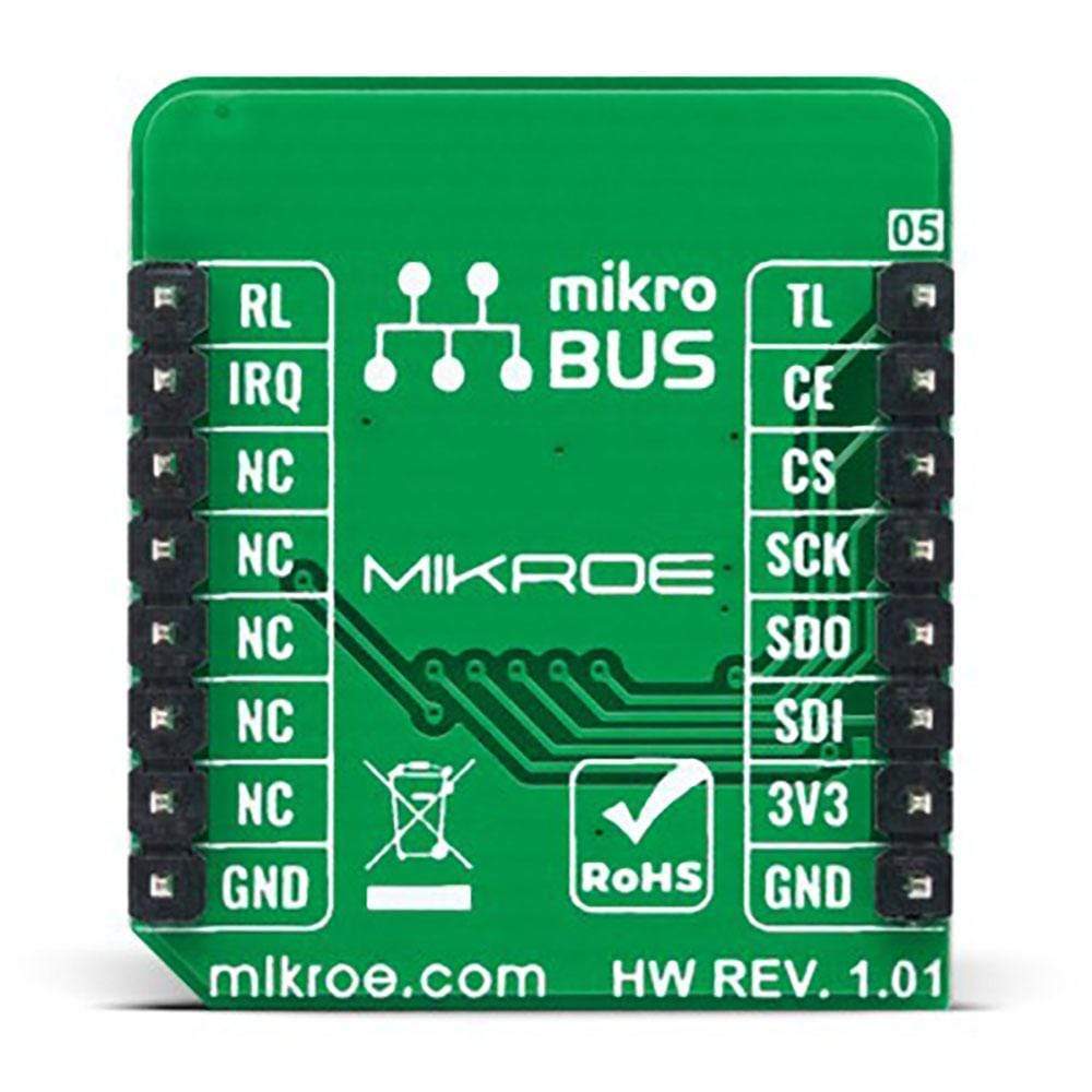
PINOUT DIAGRAM
This table shows how the pinout of the ISM Click Board™ corresponds to the pinout on the mikroBUS™ socket (the latter shown in the two middle columns).
| Notes | Pin | Pin | Notes | ||||
|---|---|---|---|---|---|---|---|
| Data Transmission Indicator | TL | 1 | AN | PWM | 16 | RL | Data Reception Indicator |
| Chip Enable | CE | 2 | RST | INT | 15 | IRQ | Interrupt |
| SPI Chip Select | CS | 3 | CS | RX | 14 | NC | |
| SPI Clock | SCK | 4 | SCK | TX | 13 | NC | |
| SPI Data OUT | SDO | 5 | MISO | SCL | 12 | NC | |
| SPI Data IN | SDI | 6 | MOSI | SDA | 11 | NC | |
| Power Supply | 3.3V | 7 | 3.3V | 5V | 10 | NC | |
| Ground | GND | 8 | GND | GND | 9 | GND | Ground |
ONBOARD SETTINGS AND INDICATORS
| Label | Name | Default | Description |
|---|---|---|---|
| LD1 | PWR | - | Power LED Indicator |
| LD2 | INT | - | Interrupt LED Indicator |
| LD3 | TX | - | Data Transmission LED Indicator |
| LD4 | RX | - | Data Reception LED Indicator |
ISM CLICK ELECTRICAL SPECIFICATIONS
| Description | Min | Typ | Max | Unit |
|---|---|---|---|---|
| Supply Voltage | - | 3.3 | - | V |
| Operating Frequency Range | 2400 | - | 2527 | MHz |
| Air Data Rate | 250 | - | 2000 | Kbps |
| Operating Temperature Range | -40 | +25 | +85 | °C |
| General Information | |
|---|---|
Part Number (SKU) |
MIKROE-4625
|
Manufacturer |
|
| Physical and Mechanical | |
Weight |
0.02 kg
|
| Other | |
EAN |
8606027382765
|
Frequently Asked Questions
Have a Question?
Be the first to ask a question about this.