Overview
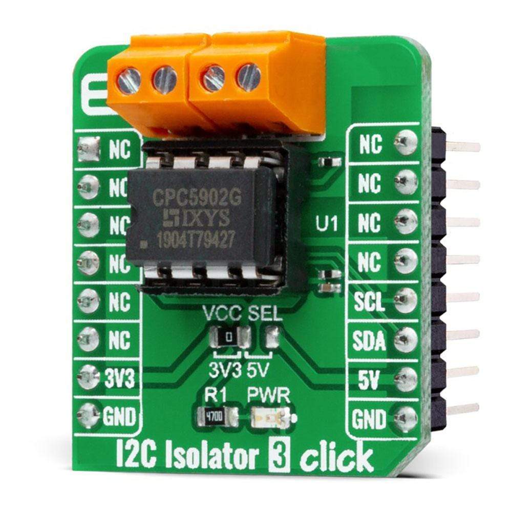
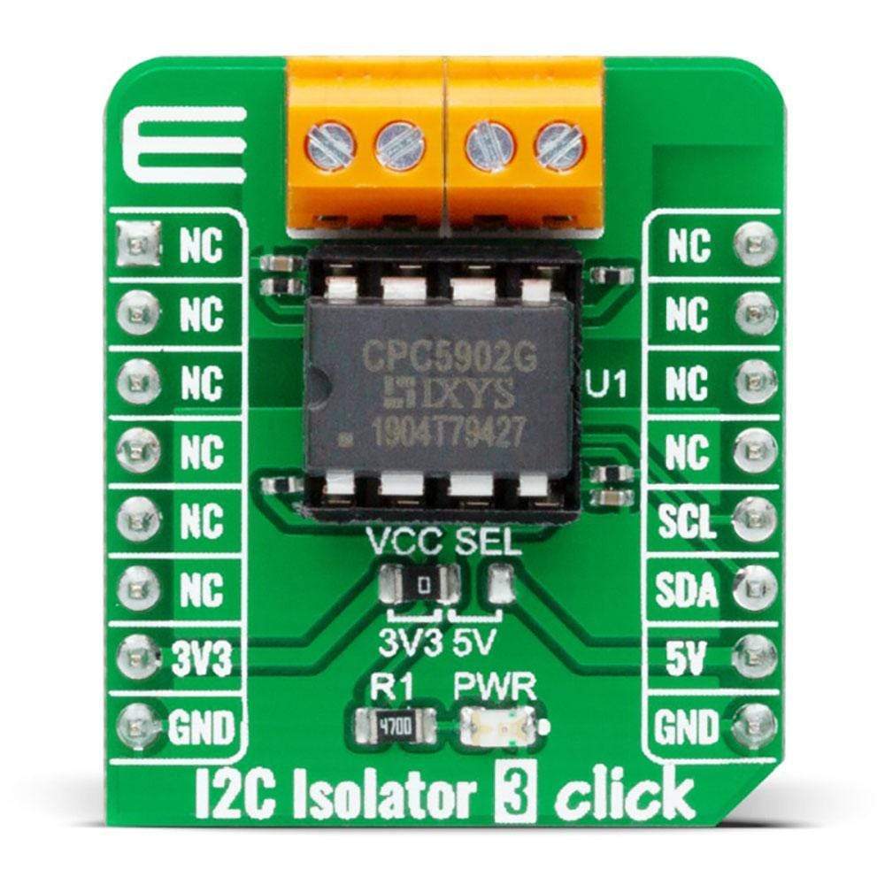
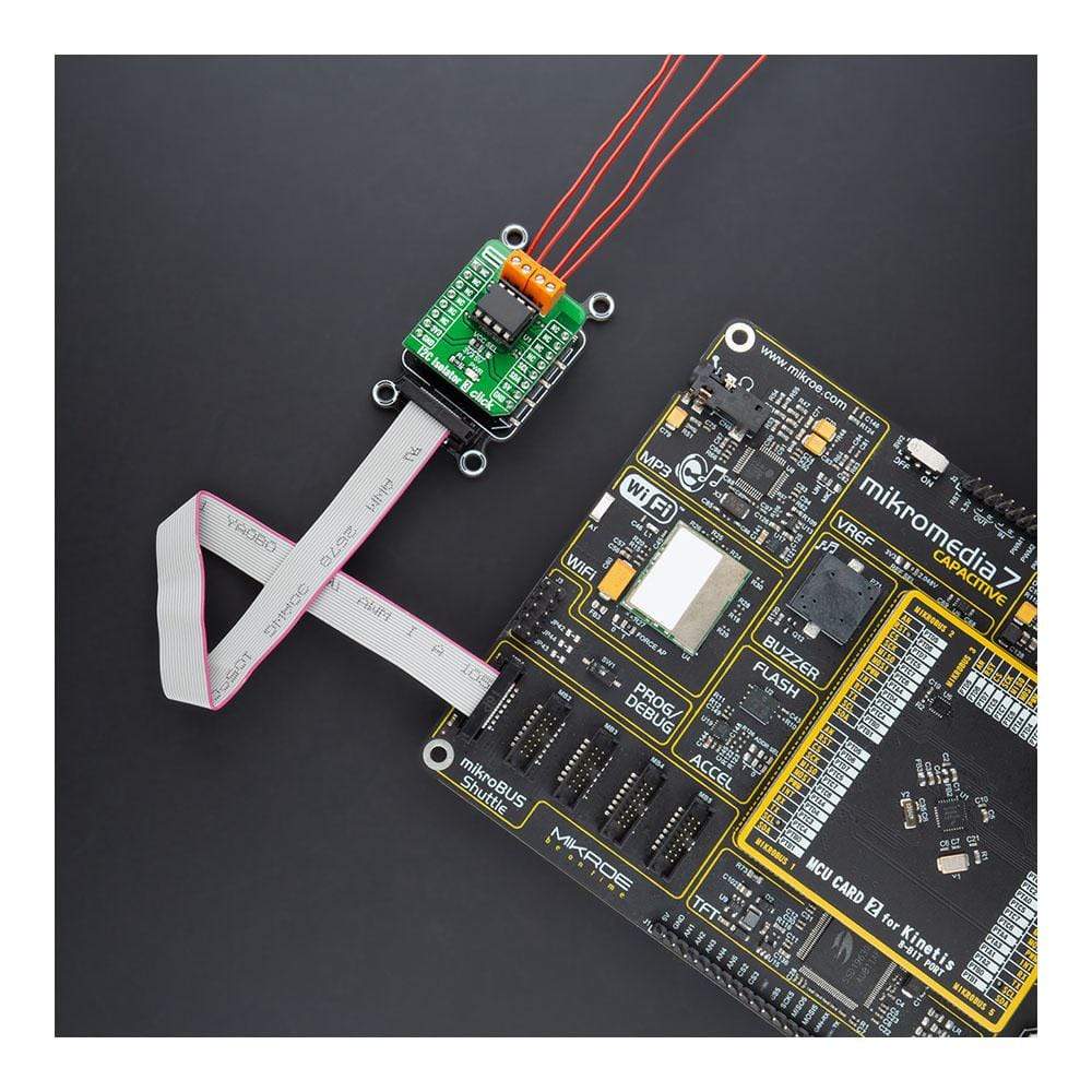
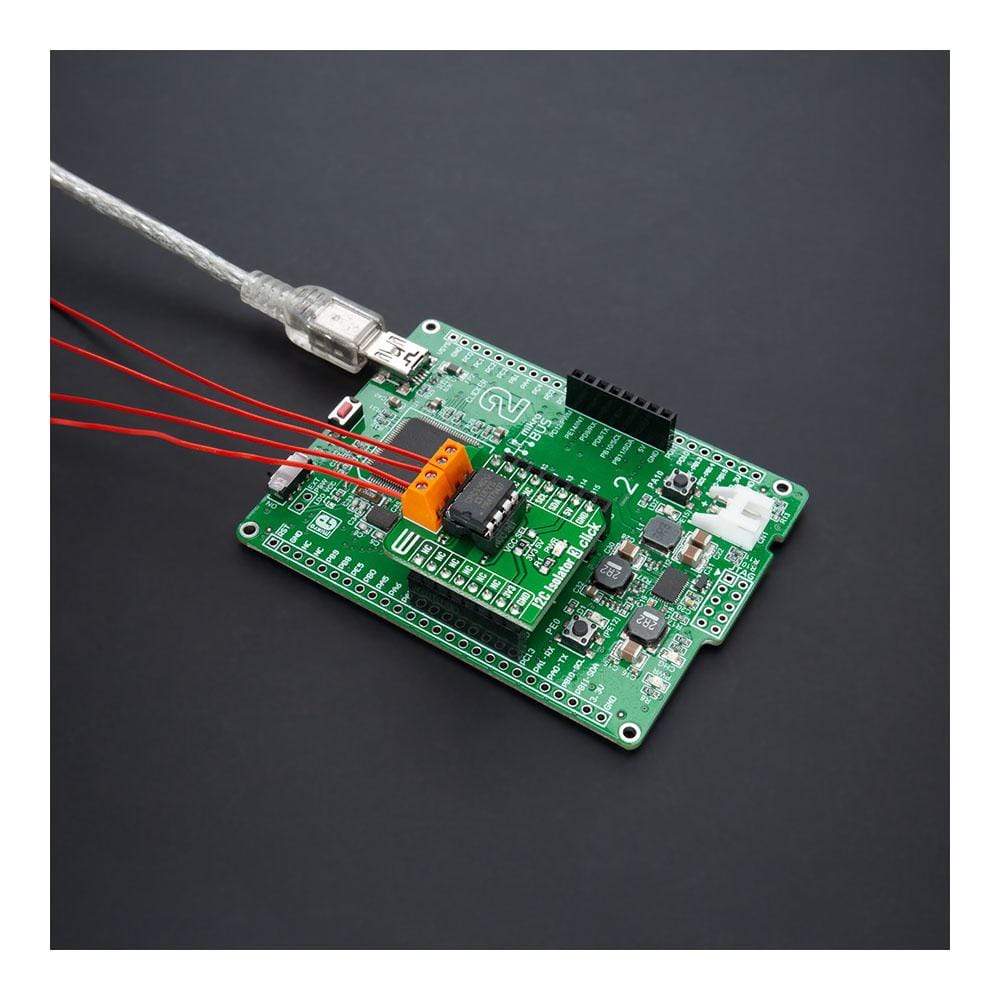
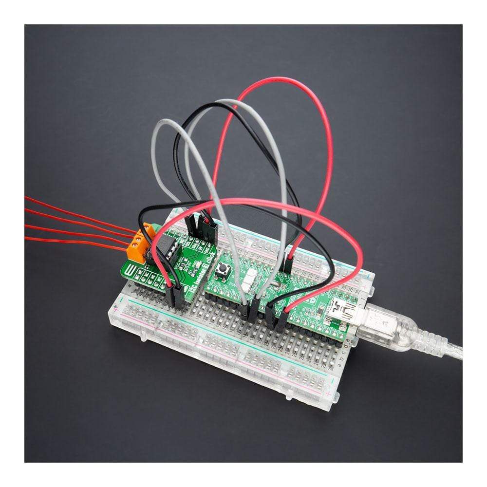
The I2C Isolator 3 Click Board™ is a compact add-on board that offers completely isolated bidirectional communication. This board features the CPC5902, a dual optically isolated bidirectional logic-bus repeater from IXYS Integrated Circuits Division. The CPC5902 pass DC signals and don’t need to be clocked periodically to sustain the logic states. It supports I2C clock stretching while providing 3750Vrms of galvanic isolation. When different supply voltages are applied on both power sides of the CPC5902, it can also function as a logic level translator for levels as low as 2.7V or as high as 5.5V. This Click Board™ is ideal for Power-over-Ethernet applications, providing buffering and isolation of the clock and data signals between MCU and the Power Supply Equipment (PSE) controller, and also suitable as an I2C bus length extender and logic-level translator.
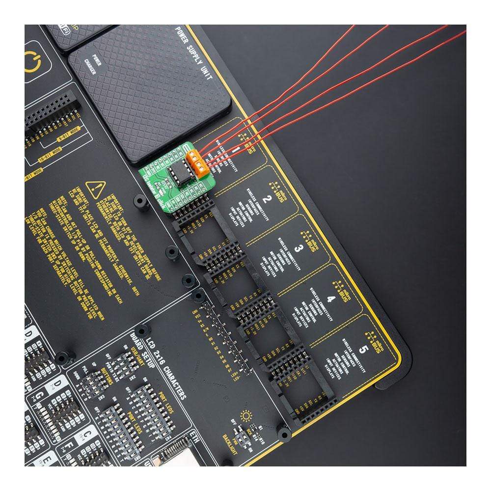
The I2C Isolator 3 Click Board™ is supported by a mikroSDK compliant library, which includes functions that simplify software development. This Click Board™ comes as a fully tested product, ready to be used on a system equipped with the mikroBUS™ socket.
Downloads
How Does The I2C Isolator 3 Click Board™ Work?
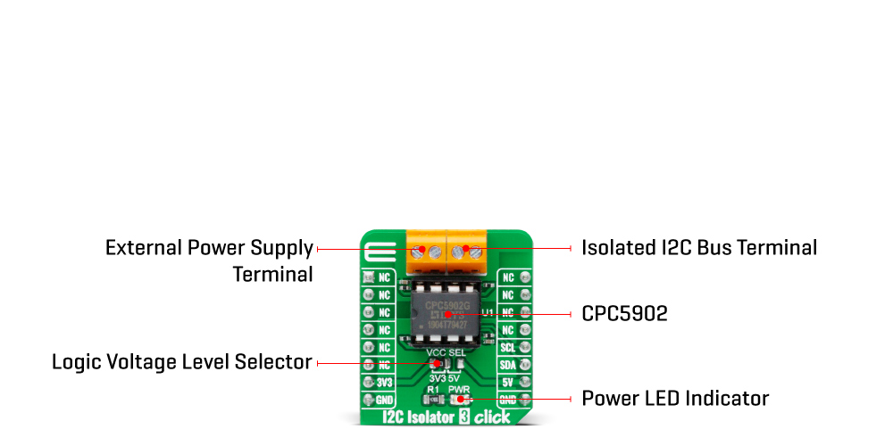
The I2C Isolator 3 Click Board™ is based on the CPC5902, a dual optically isolated bidirectional logic-bus repeater from IXYS Integrated Circuits Division. It bidirectionally buffers the two I2C signals across the isolation barrier and supports I2C clock stretching while providing 3750Vrms of galvanic isolation. After a transient interruption on either side, the buffered signals will always return to their proper value. Unlike competitive magnetically isolated digital isolators, transformers, or capacitive isolators, the CPC5902 doesn't need to be clocked periodically to sustain the logic states. Besides, it offers glitch-free operation, excellent reliability, and a long operational life. If different supply voltage levels are used at each power supply side, it can also function as a logic level translator for levels as low as 2.7V or as high as 5.5V.
This optically coupled I2C bus repeater is ideal for Power-over-Ethernet (PoE) applications, buffering and isolating the clock and data signals between the host controller and the Power Supply Equipment (PSE) controller. Additional applications include power supply high side interface, I2C bus length extender, and isolated signal monitoring and control. An extensive operational power supply range of 2.7V to 5.5V also enables I2C logic-level translation applications.
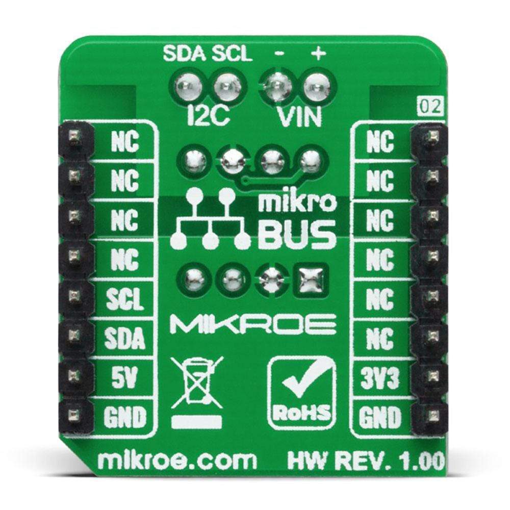
The I2C Isolator 3 Click Board™ communicates with MCU using the standard I2C 2-Wire interface and supports both Standard and Fast Mode with a transfer rate up to 400kbps. The CPC5902 is also fully compatible with any single or double wire bus in the frequency range from 0 Hz to 500 kHz, corresponding to a 400 kbps transfer rate for the I2C bus. It also possesses two terminals labelled as VIN and I2C at the bottom of the Click board™, where VIN represents the B-side power supply of the repeater, while the other I2C corresponds to the isolated bidirectional logic-bus terminal.
The I2C Isolator 3 Click Board™ is designed to operate with both 3.3V and 5V logic voltage levels selected via the VCC SEL jumper. It allows for both 3.3V and 5V capable MCUs to use the I2C communication lines properly. However, the Click board™ comes equipped with a library containing functions and an example code that can be used as a reference for further development.
SPECIFICATIONS
| Type | I2C, Isolators |
| Applications | Can be used for Power-over-Ethernet applications, providing buffering and isolation of the clock and data signals between MCU and the Power Supply Equipment (PSE) controller, and is also suitable as an I2C bus length extender and logic-level translator. |
| On-board modules | CPC5902 - a dual optically isolated bidirectional logic-bus repeater from IXYS Integrated Circuits Division |
| Key Features | The optically isolated bidirectional logic-bus repeater supports I2C clock stretching. It offers glitch-free operation, excellent reliability, and a very long operational life. |
| Interface | I2C |
| Compatibility | mikroBUS |
| Click board size | S (28.6 x 25.4 mm) |
| Input Voltage | 3.3V or 5V |
PINOUT DIAGRAM
This table shows how the pinout of the I2C Isolator 3 Click Board™ corresponds to the pinout on the mikroBUS™ socket (the latter shown in the two middle columns).
| Notes | Pin |  |
Pin | Notes | |||
|---|---|---|---|---|---|---|---|
| NC | 1 | AN | PWM | 16 | NC | ||
| NC | 2 | RST | INT | 15 | NC | ||
| NC | 3 | CS | RX | 14 | NC | ||
| NC | 4 | SCK | TX | 13 | NC | ||
| NC | 5 | MISO | SCL | 12 | SCL | I2C Clock | |
| NC | 6 | MOSI | SDA | 11 | SDA | I2C Data | |
| Power Supply | 3.3V | 7 | 3.3V | 5V | 10 | 5V | Power Supply |
| Ground | GND | 8 | GND | GND | 9 | GND | Ground |
ONBOARD SETTINGS AND INDICATORS
| Label | Name | Default | Description |
|---|---|---|---|
| LD1 | PWR | - | Power LED Indicator |
| JP1 | VCC SEL | Left | Logic Level Voltage Selection 3V3/5V: Left position 3V3, Right position 5V |
I2C ISOLATOR 3 CLICK ELECTRICAL SPECIFICATIONS
| Description | Min | Typ | Max | Unit |
|---|---|---|---|---|
| Logic Level Supply Voltage | 3.3 | - | 5 | V |
| Operating Supply Voltage | 2.7 | - | 5.5 | V |
| Isolation Voltage | 3750 | - | - | Vrms |
| I2C Clock Frequency | 0 | - | 500 | kHz |
| Operating Temperature Range | -40 | 25 | +85 | °C |
| General Information | |
|---|---|
Part Number (SKU) |
MIKROE-4467
|
Manufacturer |
|
| Physical and Mechanical | |
Weight |
0.018 kg
|
| Other | |
Country of Origin |
|
HS Code Customs Tariff code
|
|
EAN |
8606027381621
|
Warranty |
|
Frequently Asked Questions
Have a Question?
Be the first to ask a question about this.


