


Mikroelektronika d.o.o.
WiFi 11 Click Board™
WiFi 11 Click Board™
SKU: MIKROE-4245
Couldn't load pickup availability

Overview
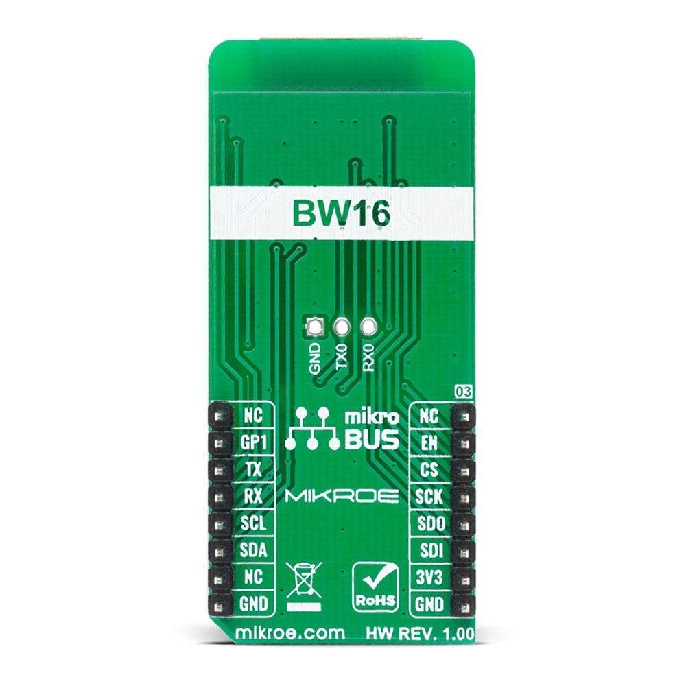
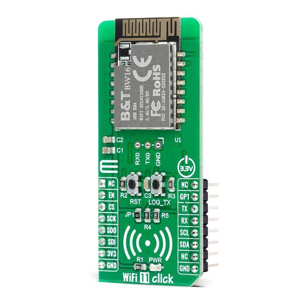
The WiFi 11 Click Board™ is a compact add-on board that contains a WiFi and Bluetooth module that has dual bands for WiFi communication. This board features the BW16, a low-power dual-band Wireless LAN (WLAN) and Bluetooth Low Energy SoC module from Shenzhen B&T Technologies Co., Ltd. This module supports the WiFi 5G and Bluetooth Low Energy 5.0, it consists of a high-performance MCU on a module named KM4, a low power MCU named KM0, WLAN (802.11 a/b/g/n) MAC, a 1T1R capable WLAN baseband, RF, Bluetooth, and peripherals. An inner antenna and many interfaces are available in this WiFi and Bluetooth module. This Click Board™ is suitable for industrial wireless control, Bluetooth gateway, security ID tags, smart home applications, and many more.
The WiFi 11 Click is supported by a mikroSDK compliant library, which includes functions that simplify software development. This Click Board™ comes as a fully tested product, ready to be used on a system equipped with the mikroBUS™ socket.
Downloads
How Does The WiFi 11 Click Board™ Work?
The WiFi 11 Click Board™ is based on the BW16, a low-power dual bands Wireless LAN (WLAN) and Bluetooth Low Energy SoC module from Ai-Thinker. The BW16 module represents a highly integrated Wi-Fi and Bluetooth SOC based on the RTL8720DN, a highly integrated Single-Chip with a low power dual bands (2.4GHz and 5GHz), Wireless LAN (WLAN), and Bluetooth Low Energy (v5.0). It consists of a high-performance MCU (ARM V8M, Cortex-M4F instruction compatible) named KM4, a low power MCU (ARM V8M, Cortex-M0 instruction compatible) named KM0, WLAN (802.11 a/b/g/n) MAC, a 1T1R capable WLAN baseband, RF, Bluetooth, and other peripherals. The BW16 integrates internal memories for complete WIFI and BLE 5.0 protocol functions. The embedded memory configuration also provides simple application developments.
The WiFi 11 Click Board™ communicates with MCU using the UART interface at 57600 bps as its default communication protocol, but it is also left the option for the user to use other interfaces such as SPI and I2C if he wants to configure the module and write the library by himself. There is also a jumper JP1 on this Click board™ that enables the necessary pull-up resistors on the SCL and SDA lines of I2C communication.
NOTE: After primary module initialization, and before any program uploading, user should write network parameters and TCP server parameters.
Additional functionality such as the Chip Enable button labelled as RST, which is used to Enable or put the module in Shut-Down mode, is provided and routed at EN pin of the mikroBUS™ socket. Alongside this pin, this Click board™ has one general purpose pin GP1 routed at the INT pin of the mikroBUS™ socket, which can be used in various cases like interrupt or some other purposes. WiFi 11 Click also has an additional header with UART RX0 and TX0 module pins on itself together with a button labelled as LOG_TX which can be used for Firmware Update or as low-power mode Wake-Up function.
The WiFi 11 Click Board™ is designed to be operated only with a 3.3V logic voltage level. A proper logic voltage level conversion should be performed before the Click board™ is used with MCUs with different logic levels. However, the Click board™ comes equipped with a library that contains easy to use functions and a usage example that may be used as a reference for further development.
SPECIFICATIONS
| Type | WiFi |
| Applications | Can be used for industrial wireless control, Bluetooth gateway, security ID tags, smart home applications, and many more. |
| On-board modules | The WiFi 11 Click Board™ is based on the BW16, a low-power dual bands Wireless LAN (WLAN) and Bluetooth Low Energy SoC module from Ai-Thinker. |
| Key Features | Ultra-low power consumption, support low-power Tx/Rx for short-range applications, support BLE, supported TrustZone-M and Secure boot, eFuse protection, and more. |
| Interface | I2C,SPI,UART |
| Compatibility | mikroBUS |
| Click board size | L (57.15 x 25.4 mm) |
| Input Voltage | 3.3V |
PINOUT DIAGRAM
This table shows how the pinout of the WiFi 11 Click Board™ corresponds to the pinout on the mikroBUS™ socket (the latter shown in the two middle columns).
| Notes | Pin | Pin | Notes | ||||
|---|---|---|---|---|---|---|---|
| NC | 1 | AN | PWM | 16 | NC | ||
| Chip Enable | EN | 2 | RST | INT | 15 | GP1 | General Purpose Pin |
| SPI Chip Select | CS | 3 | CS | RX | 14 | TX | UART TX |
| SPI Clock | SCK | 4 | SCK | TX | 13 | RX | UART RX |
| SPI Data OUT | SDO | 5 | MISO | SCL | 12 | SCL | I2C Clock |
| SPI Data IN | SDI | 6 | MOSI | SDA | 11 | SDA | I2C Data |
| Power Supply | 3.3V | 7 | 3.3V | 5V | 10 | NC | |
| Ground | GND | 8 | GND | GND | 9 | GND | Ground |
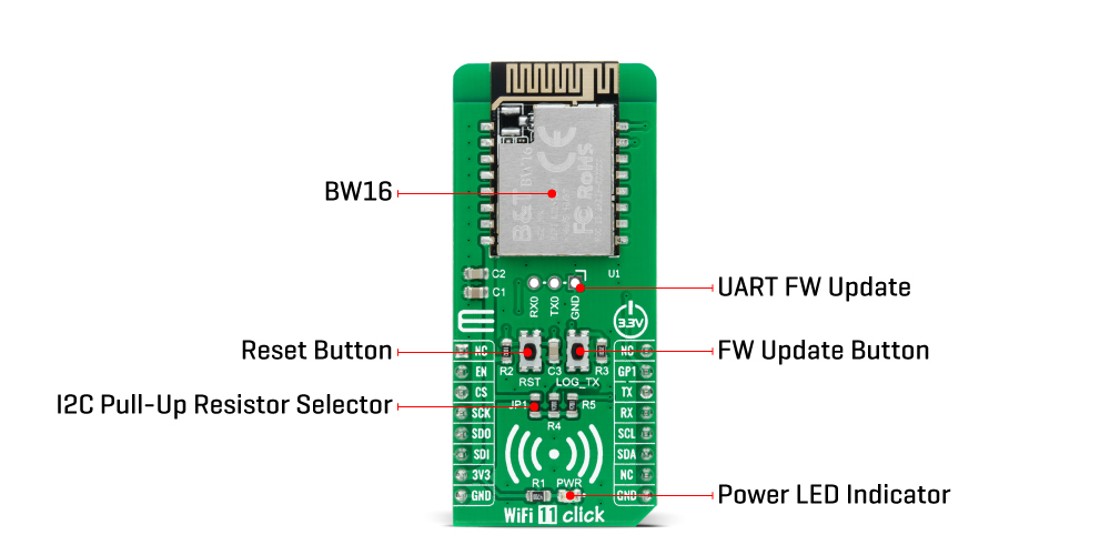
ONBOARD SETTINGS AND INDICATORS
| Label | Name | Default | Description |
|---|---|---|---|
| LD1 | PWR | - | Power LED Indicator |
| JP1 | - | - | I2C Pull-Up Resistor Selector |
| J1 | M1X3 | - | UART FW Update Header |
| T1 | LOG_TX | - | FW Update Button |
| T2 | RST | - | Chip Enable Button |
WIFI 11 CLICK ELECTRICAL SPECIFICATIONS
| Description | Min | Typ | Max | Unit |
|---|---|---|---|---|
| Supply Voltage | - | 3.3 | - | V |
| Frequency Range | 2.412 / 5.180 | - | 2.484 / 5.825 | GHz |
| Receiver Sensitivity | - | -92 | - | dBm |
| Transmit Power | - | 7±2 | - | dBm |
| Operating Temperature Range | -20 | - | +85 | °C |
| General Information | |
|---|---|
Part Number (SKU) |
MIKROE-4245
|
Manufacturer |
|
| Physical and Mechanical | |
Weight |
0.021 kg
|
| Other | |
EAN |
8606027380495
|
Frequently Asked Questions
Have a Question?
Be the first to ask a question about this.