Overview
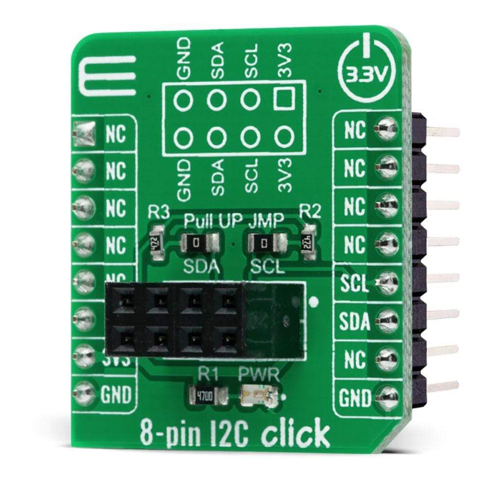
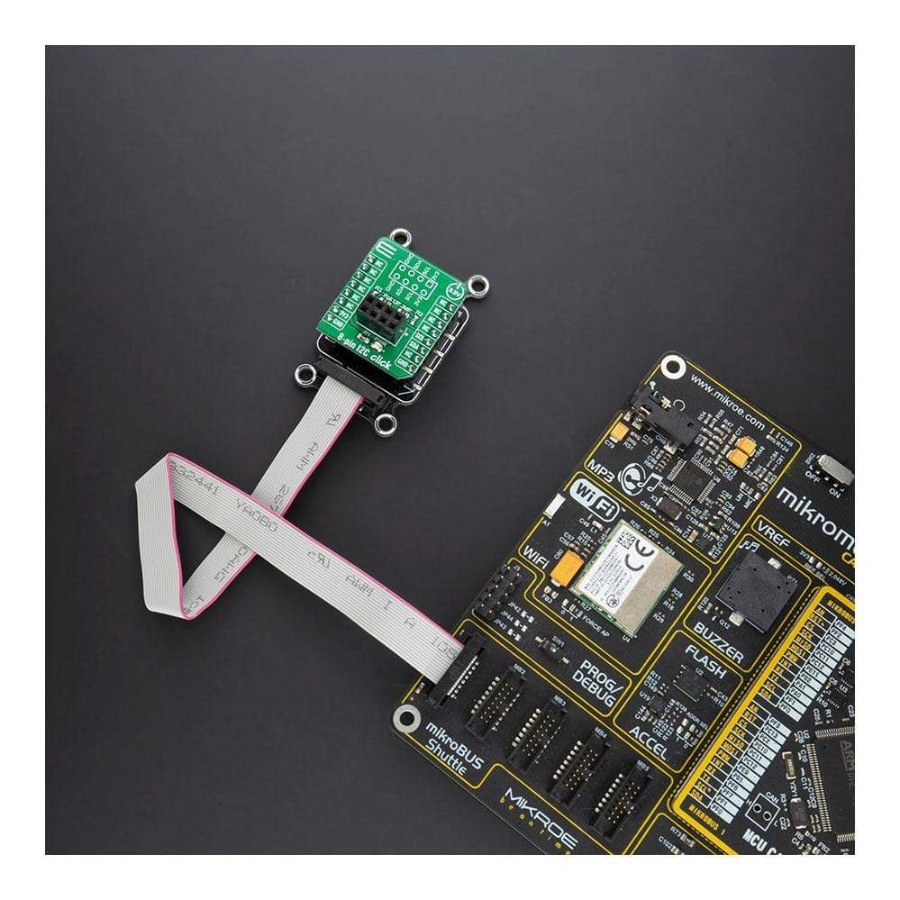
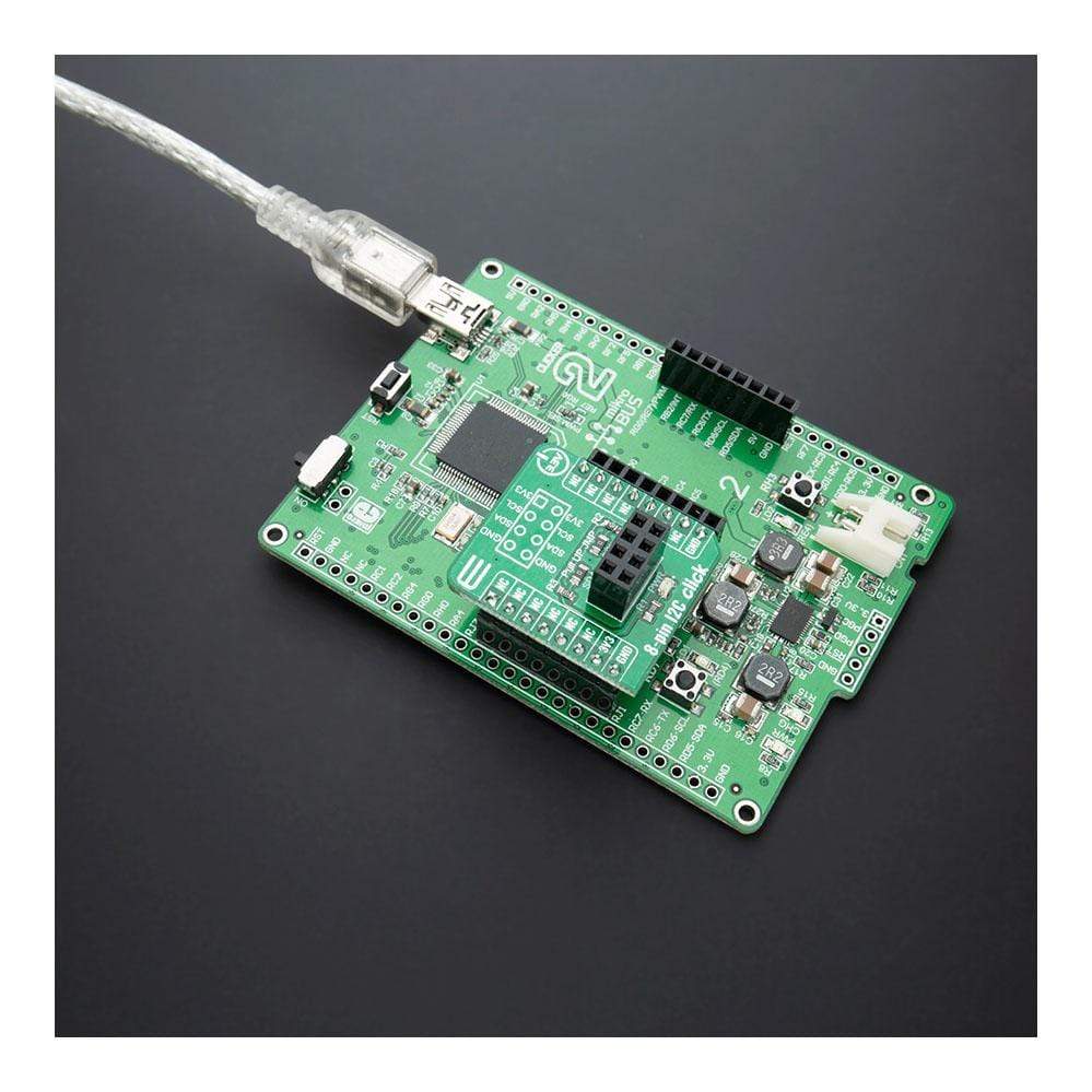
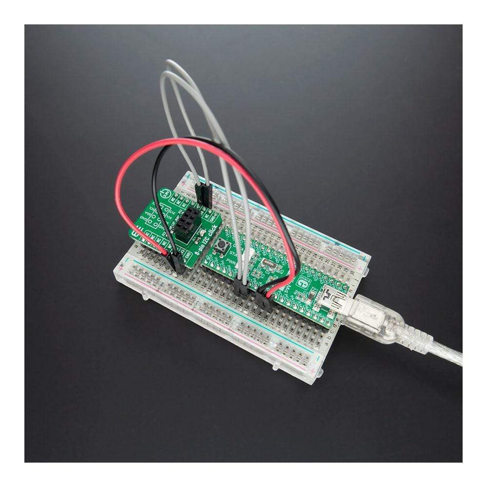
The 8-pin I2C Click Board™ is a compact add-on board that represents a breakout board that simplifies the connection of add-on boards with an 8-pin Female Connector to mikroBUS™ socket. This board can be used as I2C Adapter with no main component on itself, with only an onboard connector for connection establishing. The 8-pin I2C Click Board™ has no regional restrictions, no need for special permits, and it is possible to use this Click Board™ worldwide. Being compatible with MFI (Made for iPod) is the most important feature of the 8-pin I2C Click Board™ which ensures its proper operation with additional Apple accessories. This Click Board™ is suitable for expanding the connectivity of the development system with the mikroBUS™, and ideal for communication with numerous devices that share the identical slave address on the same bus.
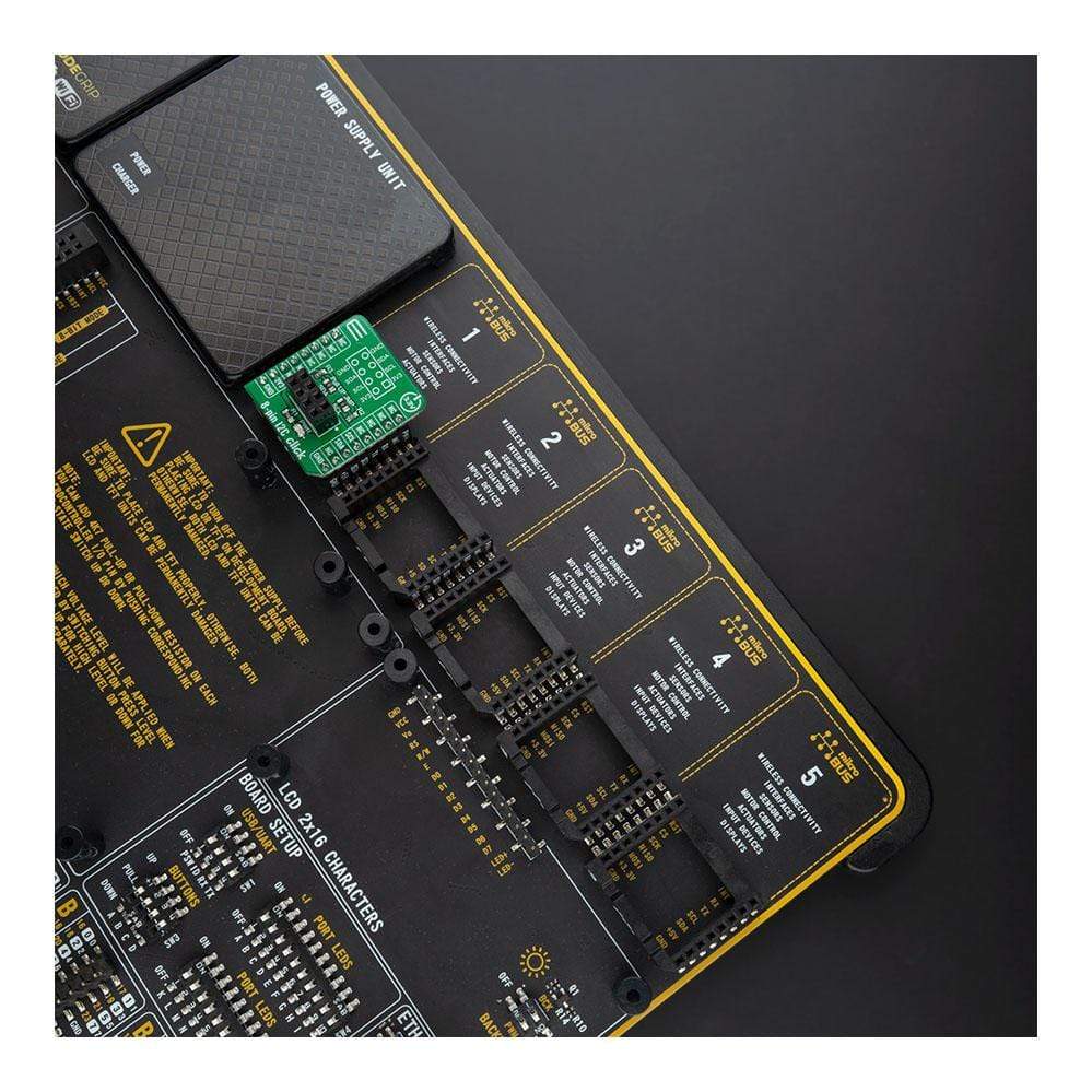
The 8-pin I2C Click Board™ is supported by a mikroSDK compliant library, which includes functions that simplify software development. This Click Board™ comes as a fully tested product, ready to be used on a system equipped with the mikroBUS™ socket.
Downloads
How Does The 8-Pin I2C Click Board™ Work?
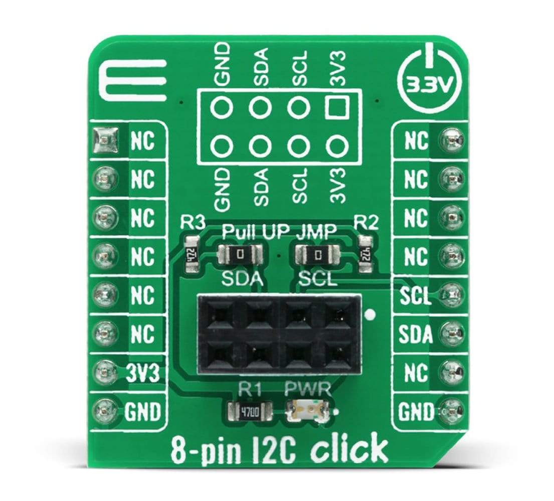
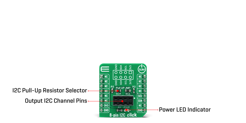
The 8-pin I2C Click Board™ is a breakout board that simplifies the connection of add-on boards to the mikroBUS™ socket. This Click board™ represents a small-size PCB that can be connected to the mikroBUS™ socket like any other Click board™, with a 2x4 female header placed on itself. Each of the header pins is corresponding to a pin on the mikroBUS™ socket being used such as I2C lines (SCL, SDA) with two jumpers for the I2C lines pull-up function selection, 3V3 power supply, and ground. This Click board™ allows easy pin access and manipulation while retaining a perfect connection quality at all times.
Being compatible with Apple's MFI is the most important feature of the 8-pin I2C Click board™ which ensures its proper operation with additional Apple accessories. The name is a shortened version of the long-form Made for iPod, the original program that ultimately became MFI which refers to peripherals that work with Apple's iPod, iPad, and iPhone.
The 8-pin I2C Click Board™ communicates with MCU using the standard I2C 2-Wire interface. Lines of the mikroBUS™ to which this Click board™ is attached, are shared through the top 8-pin female header, which mirrors the pins of the connected mikroBUS™ socket. The 8-pin I2C Click also shares the 3V3 power rails, which makes it compatible with any other power compatible Click board™ and development systems.
The 8 pin I2C click Board™ is designed to be operated only with a 3.3V logic voltage level. A proper logic voltage level conversion should be performed before the Click board™ is used with MCUs with different logic voltage levels. However, the Click board™ comes equipped with a library that contains easy to use functions and a usage example that may be used as a reference for the development.
SPECIFICATIONS
| Type | Adapter |
| Applications | Can be used for for expanding the connectivity of the development system with the mikroBUS™, and ideal for communication with numerous devices that share the identical slave address on the same bus. Compatible with MFI (Made For iPod) |
| On-board modules | 8-pin I2C Click is a compact add-on board that represents a breakout board that simplifies the connection of add-on boards with 8 pin Female Connector to mikroBUS™ socket. |
| Key Features | MFI compatibility, no regional restrictions, expanding connectivity, retaining a perfect connection quality at all times, and more. |
| Interface | I2C |
| Compatibility | mikroBUS |
| Click board size | S (28.6 x 25.4 mm) |
| Input Voltage | 3.3V |
PINOUT DIAGRAM
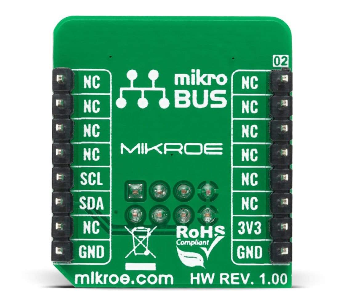
This table shows how the pinout of the 8 pin I2C click Board™ corresponds to the pinout on the mikroBUS™ socket (the latter shown in the two middle columns).
| Notes | Pin |
 |
Pin | Notes | |||
|---|---|---|---|---|---|---|---|
| NC | 1 | AN | PWM | 16 | NC | ||
| NC | 2 | RST | INT | 15 | NC | ||
| NC | 3 | CS | RX | 14 | NC | ||
| NC | 4 | SCK | TX | 13 | NC | ||
| NC | 5 | MISO | SCL | 12 | SCL | I2C Clock | |
| NC | 6 | MOSI | SDA | 11 | SDA | I2C Data | |
| Power Supply | 3.3V | 7 | 3.3V | 5V | 10 | NC | |
| Ground | GND | 8 | GND | GND | 9 | GND | Ground |
ONBOARD SETTINGS AND INDICATORS
| Label | Name | Default | Description |
|---|---|---|---|
| LD1 | PWR | - | Power LED Indicator |
| J1 | HF 2x4 | - | 8 pin Female Connector(MFI) |
| JP1-JP2 | - | - | I2C Pull-Up Resistor Selector |
| General Information | |
|---|---|
Part Number (SKU) |
MIKROE-4241
|
Manufacturer |
|
| Physical and Mechanical | |
Weight |
0.017 kg
|
| Other | |
Country of Origin |
|
HS Code Customs Tariff code
|
|
EAN |
8606027380525
|
Warranty |
|
Frequently Asked Questions
Have a Question?
Be the first to ask a question about this.

