

Mikroelektronika d.o.o.
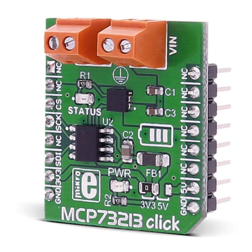
MCP73871 Click Board™
MCP73871 Click Board™
SKU: MIKROE-2858
Couldn't load pickup availability
Key Features
Overview
The MCP73871 Click Board™ is a fully integrated solution for system power delivery and Li-Po/Li-Ion battery charge management. The Click Board™ features many Li-Po/Li-Ion battery charging optimisation, used to maximise the battery life. Some of the MCP73871 Click Board™ features include constant current and voltage charging algorithms, over-voltage protection, automatic end of charge control, automatic recharge feature, preconditioning for depleted cells and thermal management.
Downloads
The features this device has, coupled with the ability to simultaneously power up the system load and charge the connected battery, make this click a perfect solution for powering up many different battery-operated builds and projects, which use a rechargeable Li-Po/Li-Ion battery, but can also switch to an external power source.
How Does The MCP73871 Click Board™ Work?
The MCP73871 Click Board™ uses the MCP73871 device, a system load sharing and Li-Po/Li-Ion battery charge management integrated circuit from Microchip. This device completely manages the power distribution, utilizing many different steps in this process.
The input voltage is constantly monitored and with no battery connected or with a battery element which is deeply depleted, the power to the connected load will be delivered straight from the external power supply, provided from the 5V rail of the mikroBUS™ socket. The current that can be delivered in this mode, depends on the limiting factor selected by the PRG2 pin. If the PRG2 pin is set to a LOW logic level, the current will be limited to 80mA - 100mA. If the PRG2 pin is set to a HIGH logic level, the current supplied to the load will be limited to 400mA - 500mA.
There are several conditions set by the MCP73871 device, that define the behavior of the power management logic. If there is a Li-Po/Li-Ion battery connected to the battery connector, the charging procedure will go through the following steps:
- If the connected battery is deeply depleted and the CE (Charge Enable) pin is set to a HIGH logic level, the preconditioning mode is activated. The charging current is only a fraction of the regulated charging current, used for fast charging, preventing battery damage and overheating.
- If the battery voltage is above the preconditioning threshold voltage set by the MCP73871 device, the fast charging will begin, and the charging current is set by the PRG2 pin, like described above and a voltage equal to 4.35V, as per factory settings of the MCP73871 IC.
- When the charging complete conditions are met, the charger circuit will stop the charging process. The battery voltage is monitored, and when it falls under the recharge threshold, another charging cycle will be repeated.
- During all the charging modes, the temperature of the MCP73871 die is monitored, so the charging current is regulated accordingly. The overtemperature protection will put the device in the shutdown mode, preventing damage.
- If the Timer is enabled by the TE pin, it will be used to limit the charging time, if the battery voltage never reaches the end-of-charge condition.
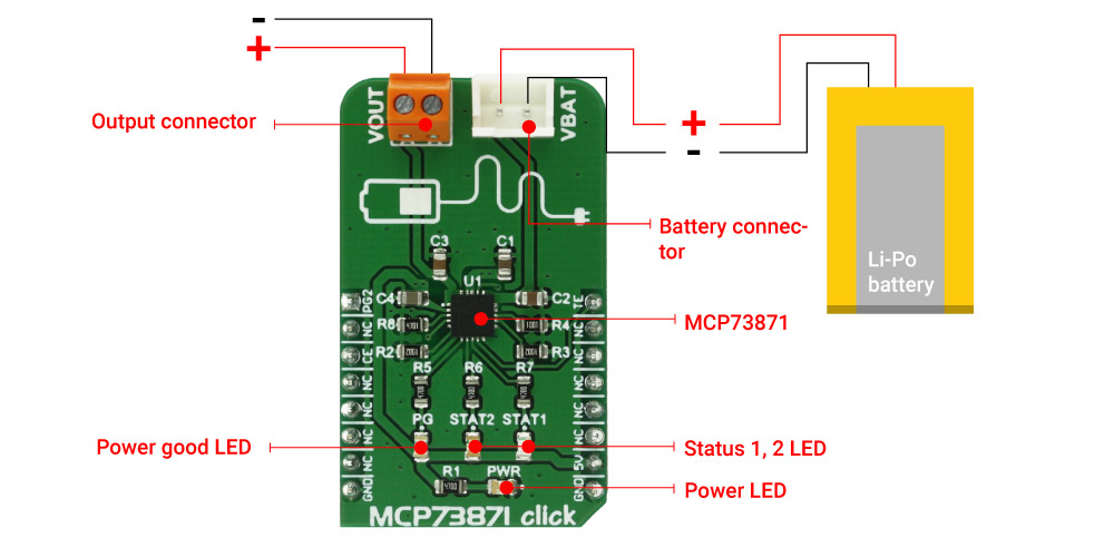
The MCP73871 power-sharing system logic, enables to simultaneously charge and power up the system load, connected to the onboard output screw terminal. The power-sharing system is active at all times and always prioritizes connected load over the battery charging. Li-Po/Li-Ion battery can be connected to the onboard 2.54mm two-pin header. There are three LEDs that are used to indicate power good status, as well as the charging status. The status LED signalization is explained in the Status LED table, below.
SPECIFICATIONS
| Type | Battery charger |
| Applications | The MCP73871 Click Board™ is a perfect solution for powering up many different battery-operated builds and projects, which are powered up by a rechargeable Li-Po/Li-Ion battery, but can also switch to an external power source while charging the battery. |
| On-board modules | Microchip's MCP73871 - Stand-Alone System Load Sharing and Li-Ion/Li-Po Battery Charge Management Controller |
| Key Features | Ability to simultaneously power up the system load and charge the connected Li-Ion/Li-Po battery by applying optimized battery charging algorithm. |
| Interface | GPIO |
| Compatibility | mikroBUS |
| Click board size | M (42.9 x 25.4 mm) |
| Input Voltage | 5V |
PINOUT DIAGRAM
This table shows how the pinout on MCP73871 click corresponds to the pinout on the mikroBUS™ socket (the latter shown in the two middle columns).
| Notes | Pin | Pin | Notes | ||||
|---|---|---|---|---|---|---|---|
| Set Charging Current | PG2 | 1 | AN | PWM | 16 | TE | Enable Safety Timer |
| NC | 2 | RST | INT | 15 | NC | ||
| Charge Enable | CE | 3 | CS | RX | 14 | NC | |
| NC | 4 | SCK | TX | 13 | NC | ||
| NC | 5 | MISO | SCL | 12 | NC | ||
| NC | 6 | MOSI | SDA | 11 | NC | ||
| NC | 7 | 3.3V | 5V | 10 | +5V | Power Supply | |
| Ground | GND | 8 | GND | GND | 9 | GND | Ground |
MCP73871 CLICK ELECTRICAL SPECIFICATIONS
| Description | Min | Typ | Max | Unit |
|---|---|---|---|---|
| Charge Current (if PG2 is low) | 80 | 100 | mA | |
| Charge current (if PG2 is high) | 400 | 500 | mA |
ONBOARD SETTINGS AND INDICATORS
| Label | Name | Default | Description |
|---|---|---|---|
| LD1 | PWR | - | Power LED indicator, green |
| LD2 | PG | - | Power good LED, blue |
| LD3 | STAT2 | - | Status LED, green |
| LD4 | STAT1 | - | Status LED, red |
| J1 | VBAT | - | Battery connector |
| TB1 | VOUT | - | External load connector |
STATUS LEDS TABLE
| Charge Cycle State | STAT1 | STAT2 | PG |
|---|---|---|---|
| Shutdown (VCC=VBAT) | Off | Off | Off |
| Shutdown (CE=L) | Off | Off | On |
| Preconditioning | On | Off | On |
| Constant Current | On | Off | On |
| Constant Voltage | On | Off | On |
| Charge Complete - Standby | Off | On | On |
| Temperature Fault | On | On | On |
| Timer Fault | On | On | On |
| Low Battery Output | On | Off | Off |
| No Battery Present | Off | Off | On |
| No Input Power Present | Off | Off | Off |
| General Information | |
|---|---|
Part Number (SKU) |
MIKROE-2858
|
Manufacturer |
|
| Physical and Mechanical | |
Weight |
0.02 kg
|
| Other | |
EAN |
8606018712113
|
Frequently Asked Questions
Have a Question?
Be the first to ask a question about this.