


Mikroelektronika d.o.o.
IqRF 2 Click Board™
IqRF 2 Click Board™
SKU: MIKROE-2587
Couldn't load pickup availability
Overview
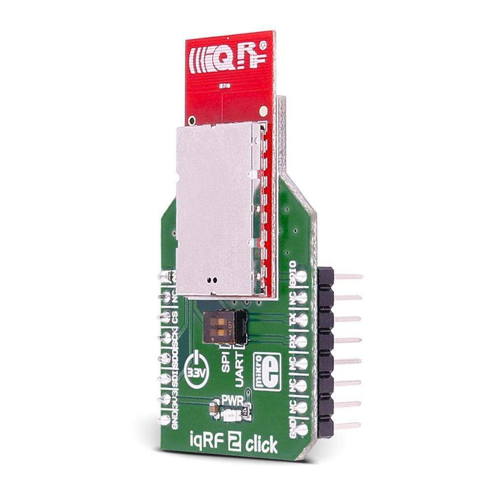
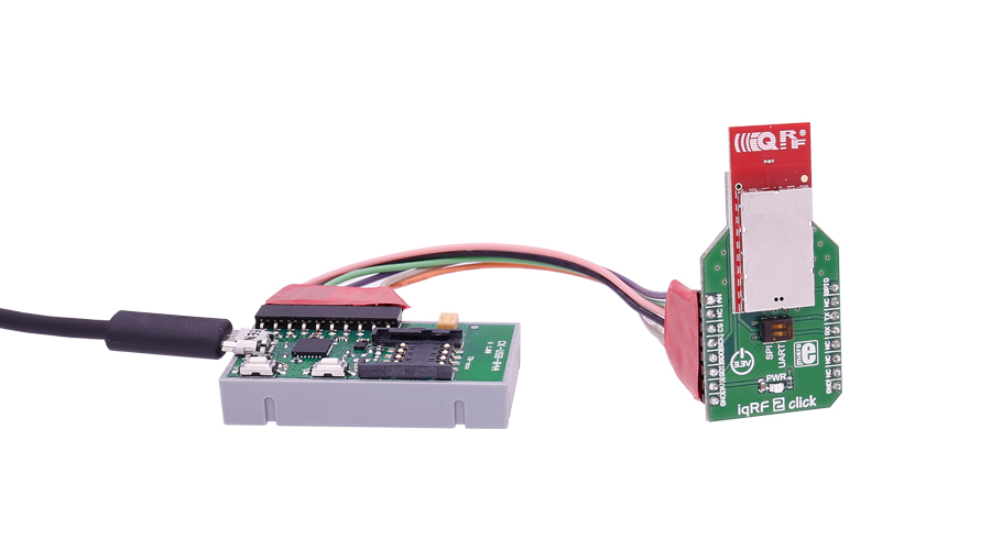
The IQRF 2 Click Board™ carries the DCTR-72DAT RF transceiver, operating in the 868/916 MHz frequency. The Click Board™ is designed to run on a 3.3V power supply.
It communicates with the target microcontroller over SPI or UART interface, with additional functionality provided by the following pins on the MikroBUSline: AN, PWM.
Downloads
The IQRF 2 Click Board™ carries the DCTR-72DAT RF transceiver, operating in the 868/916 MHz frequency. The click is designed to run on a 3.3V power supply. It communicates with the target microcontroller over SPI or UART interface, with additional functionality provided by the following pins on the mikroBUS™ line: AN, PWM.
Module Features
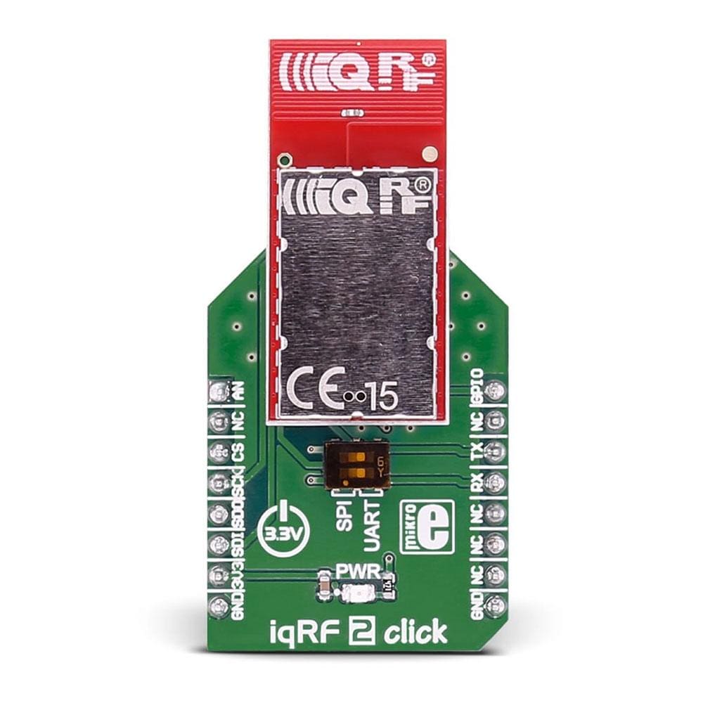
DCTR-72DAT is an RF transceiver operating in the 868/916 MHz license-free ISM (Industry, Scientific, and Medical) frequency band. Its highly integrated ready-to-use design containing MCU, RF circuitry, serial EEPROM and optional onboard antenna requires no external components.
How Does The IQRF 2 Click Board™ Work?
The DCTR-72DAT module's highly integrated ready-to-use design containing MCU, RF circuitry, integrated LDO regulator, serial EEPROM, optional temperature sensor and optional onboard antenna requires no external components.
It has extended RF power results in higher RF range. The ultra-low power consumption fits for battery powered applications.
The module with a built-in operating system significantly reduces application development time. Optional DPA framework supports applications even without programming.
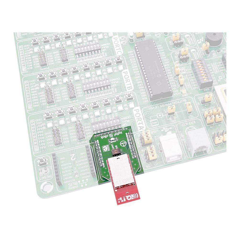
To upload application codes in DCTRs and configure DCTR parameters, CK-USB-04A kit is intended. When the application is uploaded to the IQRF it can be put in microBUS™ socket and communicate with it with MCU.
To upload the firmware put the jumpers in the SPI position.
To use our LibStock library examples the jumpers need to be in UART position.
SPECIFICATIONS
| Type | Sub-1 GHz Transceievers |
| Applications | Point-to-point or network wireless connectivity, Telemetry, AMR (automatic meter reading), WSN (wireless sensor network), Building automation, Street lighting control, etc. |
| On-board modules | DCTR-72DAT RF transceiver |
| Key Features | Selectable RF band 868 / 916 MHz, multiple channels |
| Interface | Analog,GPIO,SPI,UART |
| Compatibility | mikroBUS |
| Click board size | M (42.9 x 25.4 mm) |
| Input Voltage | 3.3V |
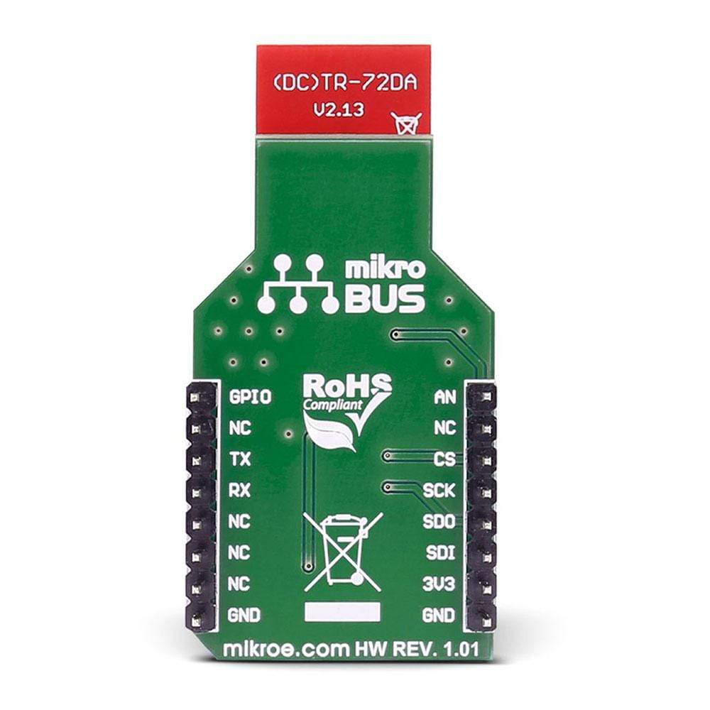
PINOUT DIAGRAM
This table shows how the pinout of the IQRF 2 Click Board™ corresponds to the pinout on the mikroBUS™ socket (the latter shown in the two middle columns).
| Notes | Pin | Pin | Notes | ||||
|---|---|---|---|---|---|---|---|
| Analog pin | ADC | 1 | AN | PWM | 16 | DIN | General I/O pin |
| NC | 2 | RST | INT | 15 | NC | ||
| SPI enable | SPI_CS | 3 | CS | TX | 14 | TXD | UART transmit |
| SPI Clock | SPI_SCK | 4 | SCK | RX | 13 | RXD | UART receive |
| SPI Master Input Slave Output | SPI_MISO | 5 | MISO | SCL | 12 | NC | |
| SPI Master Output Slave Input | SPI_MOSI | 6 | MOSI | SDA | 11 | NC | |
| Power supply | +3.3V | 7 | 3.3V | 5V | 10 | NC | |
| Ground | GND | 8 | GND | GND | 9 | GND | Ground |
| General Information | |
|---|---|
Part Number (SKU) |
MIKROE-2587
|
Manufacturer |
|
| Physical and Mechanical | |
Weight |
0.019 kg
|
| Other | |
EAN |
8606018710362
|
Frequently Asked Questions
Have a Question?
Be the first to ask a question about this.