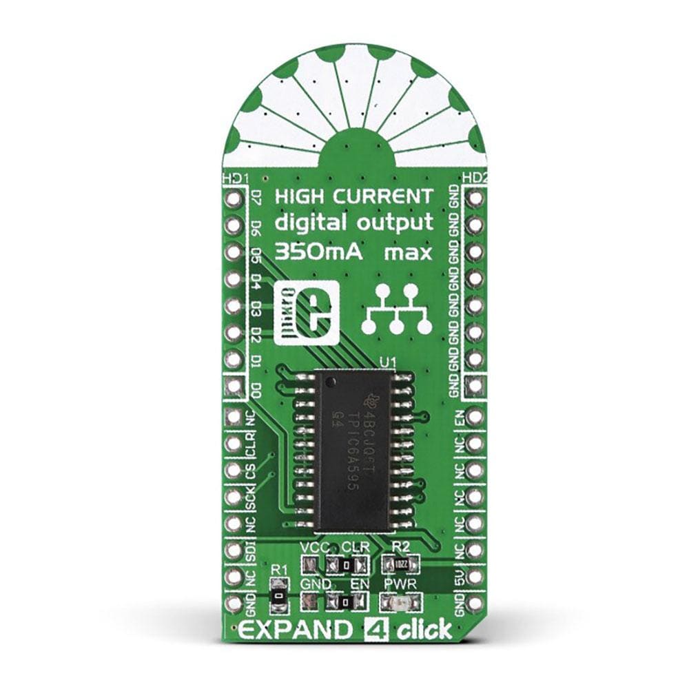
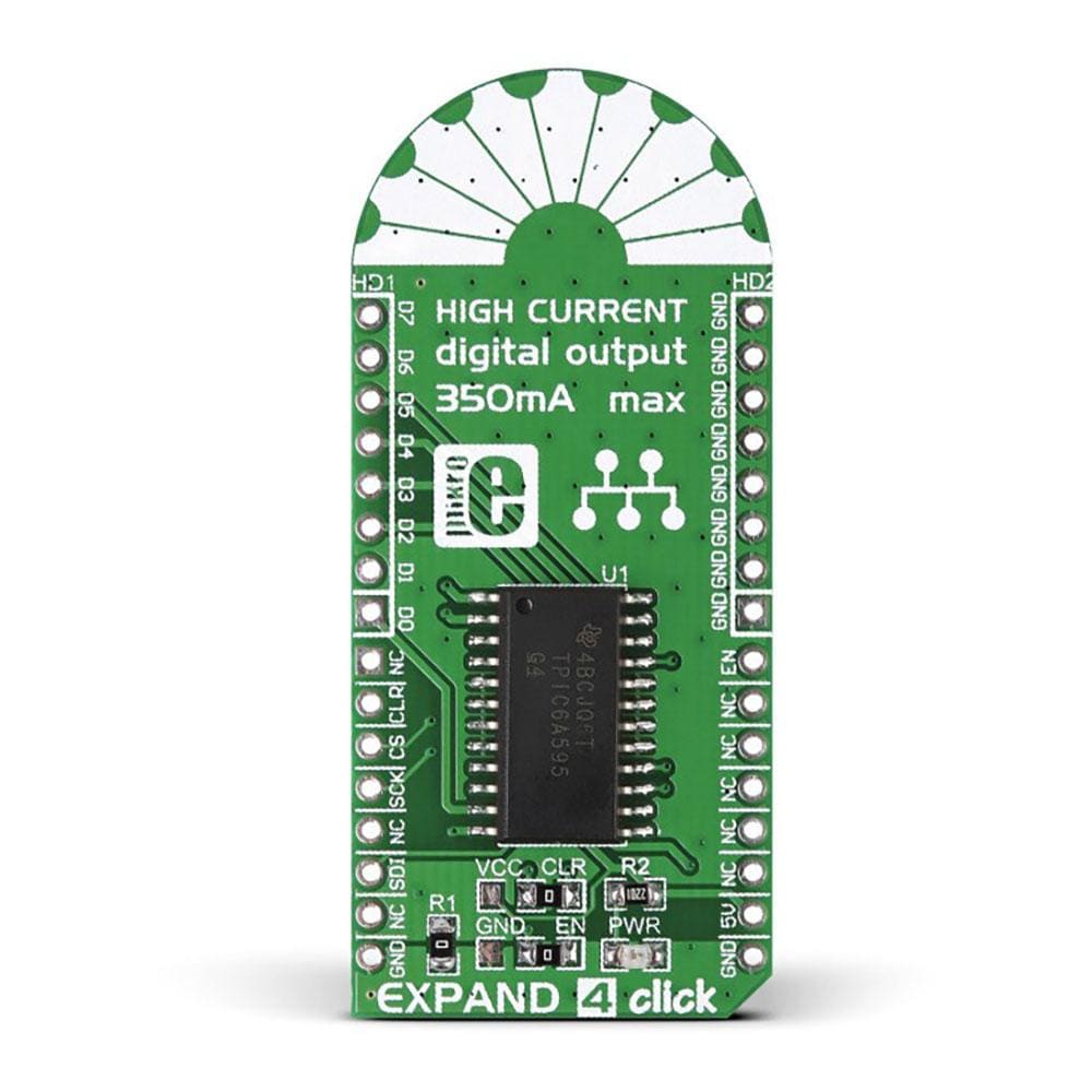
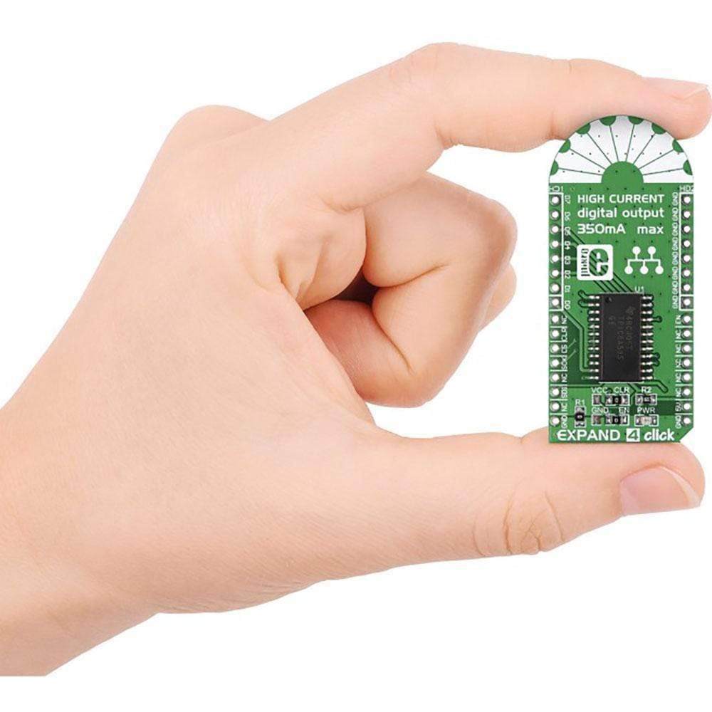
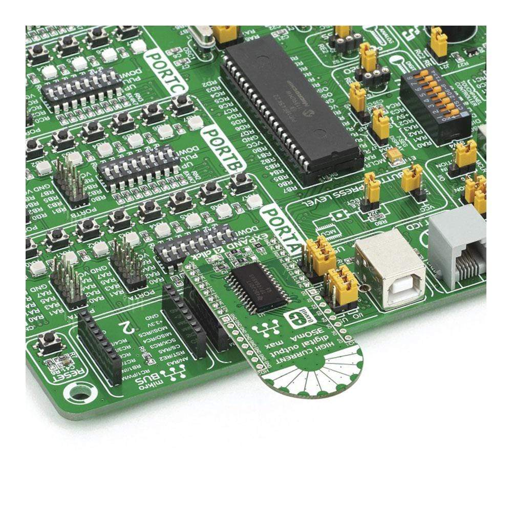
Expand 4 Click Board
Key Features
- Based on the TPCIC6A595, a chip that combines an 8-bit serial-in, parallel-out shift register with an 8-bit D-type storage register from Texas Instruments
- Each Output can sink 350mA
- mikroBUS: SPI Interface
Overview
The Expand 4 Click Board™ is intended as a port expander for connecting high-power peripherals.
It is based on the TPCIC6A595, a chip that combines an 8-bit serial-in, parallel-out shift register with an 8-bit D-type storage register.
The Expand 4 Click Board™ is based on the TPCIC6A595, a chip that combines an 8-bit serial-in, parallel-out shift register with an 8-bit D-type storage register.
Data Output
Its intended for use as a port expander for connecting high-power peripherals. On the output side it has open-drain transistors with output ratings of 50V and 350mA (these are accessed through 8 pins above the mikroBUS socket (D0-D7) with corresponding GND pins on the other side.
Data Input
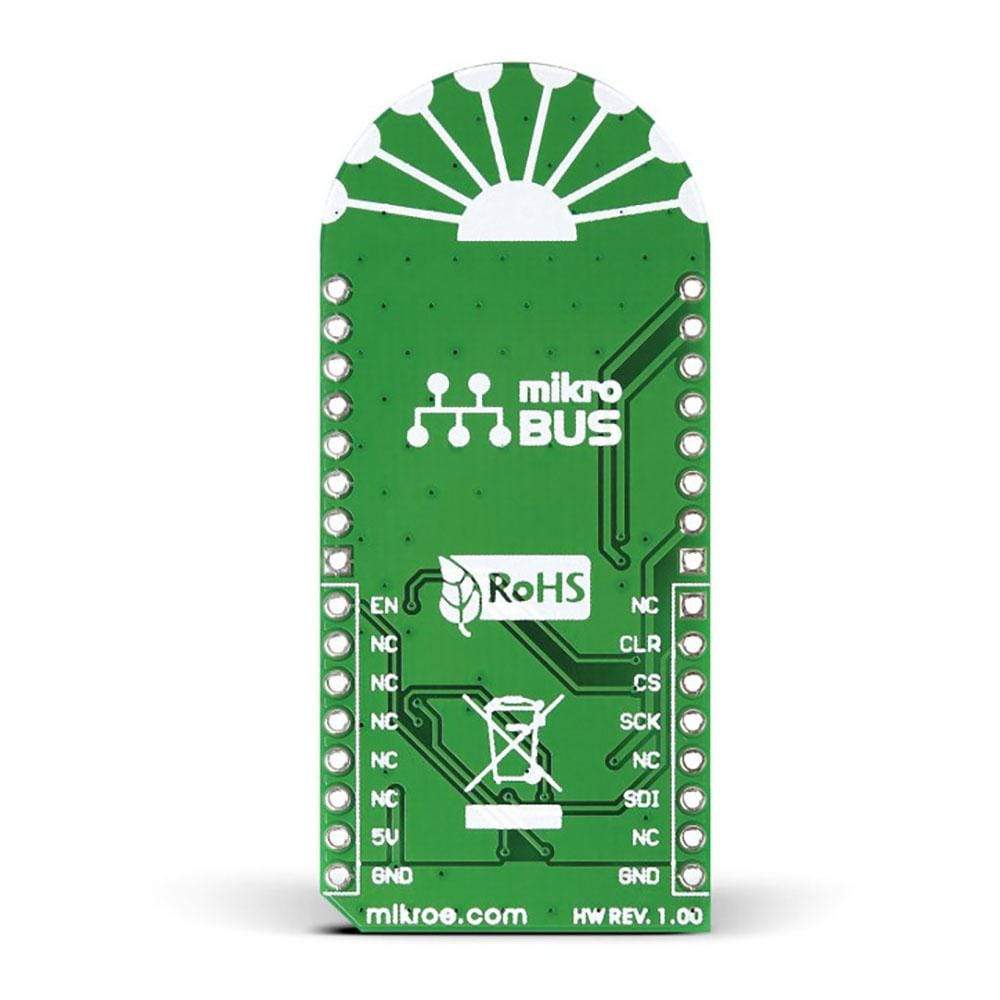
For data input, Expand 4 Click Board™ uses SPI. Additional pins include CLR IN (clear all input shift registers when held low), EN IN (sets all drain outputs to OFF when held high), and CS (provides the impulse for shifting the data from the shift to the storage register.).
Software Support
Application Task
This is an example that demonstrates the use of Expand 4 Click board. In this example, the LED pin mask is transferred via SPI bus, LEDs connected to D0-D7 pins are lit accordingly by turning ON LEDs from D0 to D7 for 3 sec. Results are being sent to the Usart Terminal where you can track their changes. All data logs on USB uart for approximately every 3 sec. when the change pin who is connected.
void application_task ( void )
{
uint8_t pin_position;
for ( pin_position = 0; pin_position < 8; pin_position++ )
{
expand4_disable_output( &expand4 );
Delay_ms( 100 );
expand4_turn_on_by_position( &expand4, pin_position );
Delay_ms( 100 );
log_printf( &logger, " D%d", pin_position );
expand4_enable_output( &expand4 );
Delay_ms( 3000 );
}
log_printf( &logger, "\n----------------------------------\n");
}
Frequently Asked Questions
Have a Question?
Be the first to ask a question about this.