


Mikroelektronika d.o.o.
Thermo 5 Click Board™
Thermo 5 Click Board™
SKU: MIKROE-2571
Couldn't load pickup availability
Overview
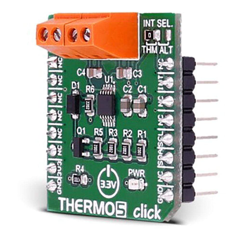
The Thermo 5 Click Board™ measures temperature in default range of 0°C to 127°C and extended range of -64°C to 191°C with ±1°C accuracy. It carries the EMC1414 temperature sensor.
The Thermo 5 Click Board™is designed to run on a 3.3V power supply. THERMO 5 Click Board™ communicates with the target microcontroller over I2C interface, with additional functionality provided by the INT pin on the mikroBUS line.
Downloads
The Thermo 5 Click Board™ can be used to measure temperatures with up to two/three externally connected diodes.
Each external diode channel is configured with Resistance Error Correction and Beta Compensation based on user settings and system requirements.
The device contains programmable High, Low, and Thermo limits for all measured temperature channels.
If the measured temperature goes below the Low limit or above the High limit, the ALERT pin can be asserted (based on user settings).
If the measured temperature meets or exceeds the Thermo Limit, the THERM pin is asserted unconditionally, providing two tiers of temperature detection.
EMC1414 FEATURES
The EMC1414 monitors four temperature channels. It provides ±1°C accuracy for both external and internal diode temperatures.
Resistance Error Correction feature automatically eliminates the temperature error caused by series resistance allowing greater flexibility in routing thermal diodes.
Beta Compensation feature eliminates temperature errors caused by low, variable beta transistors common in today's fine geometry processors.
SPECIFICATIONS
| Type | Temperature & humidity |
| Applications | Personal computers, electronics equipment, industrial controllers |
| On-board modules | EMC1414 temperature sensor |
| Key Features | ±1°C accuracy, 0.125°C resolution |
| Interface | GPIO,I2C |
| Compatibility | mikroBUS |
| Click board size | S (28.6 x 25.4 mm) |
| Input Voltage | 3.3V |
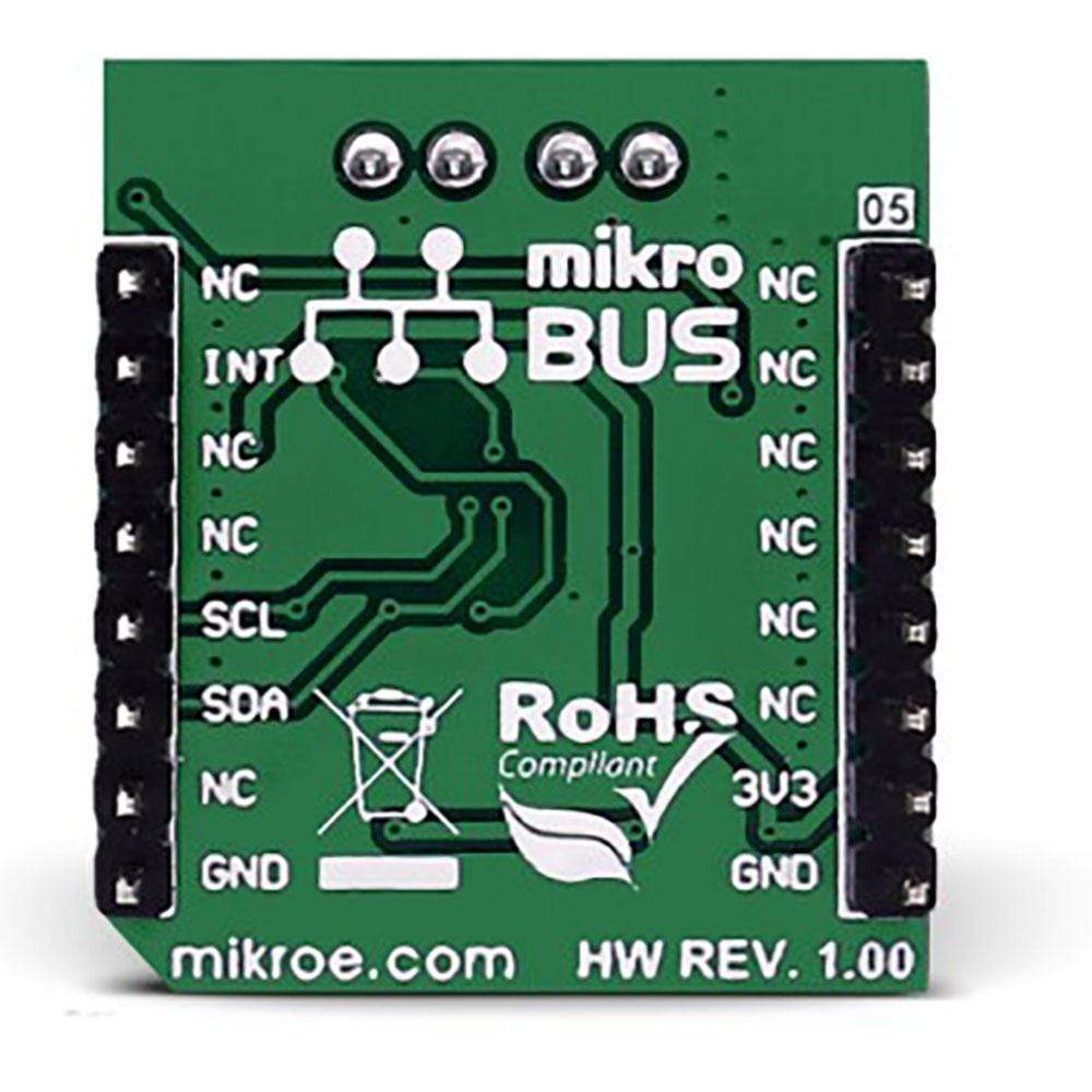
PINOUT DIAGRAM
This table shows how the pinout on the Thermo 5 Click Board™ corresponds to the pinout on the mikroBUS™ socket (the latter shown in the two middle columns).
| Notes | Pin | Pin | Notes | ||||
|---|---|---|---|---|---|---|---|
| NC | 1 | AN | PWM | 16 | NC | ||
| NC | 2 | RST | INT | 15 | INT | ALERT/THERM Interrupt Output | |
| NC | 3 | CS | TX | 14 | NC | ||
| NC | 4 | SCK | RX | 13 | NC | ||
| NC | 5 | MISO | SCL | 12 | SCL | I2C Clock | |
| NC | 6 | MOSI | SDA | 11 | SDA | I2C Data | |
| Power supply | +3.3V | 7 | 3.3V | 5V | 10 | NC | |
| Ground | GND | 8 | GND | GND | 9 | GND | Ground |
| General Information | |
|---|---|
Part Number (SKU) |
MIKROE-2571
|
Manufacturer |
|
| Physical and Mechanical | |
Weight |
0.018 kg
|
| Other | |
EAN |
8606018710300
|
Frequently Asked Questions
Have a Question?
Be the first to ask a question about this.