


Tag-Connect, LLC
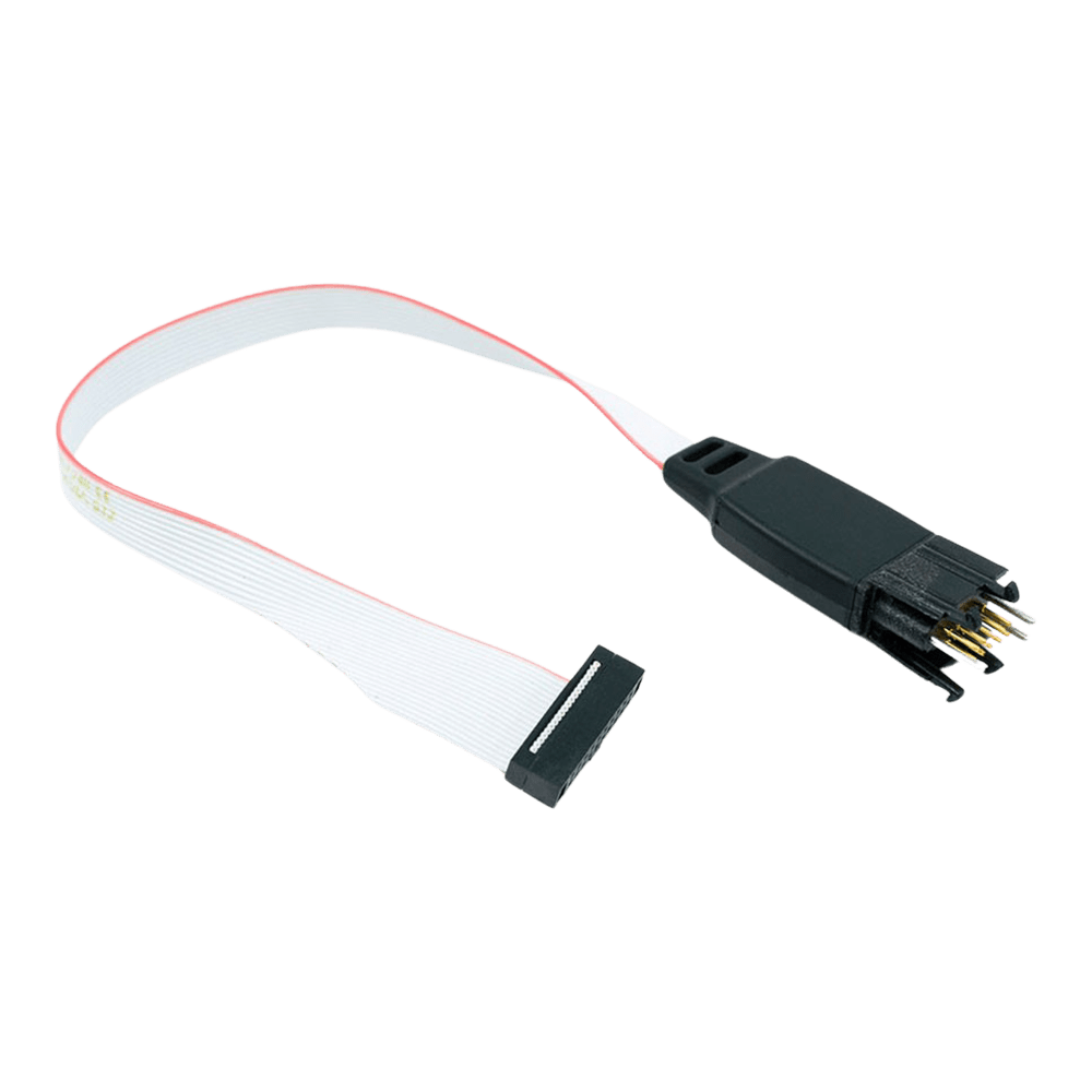
Tag Connect TC2050-IDC-050 Plug-of-Nails Debug Cable
Tag Connect TC2050-IDC-050 Plug-of-Nails Debug Cable
SKU: TC2050-IDC-050
Couldn't load pickup availability
Key Features
Overview
Downloads
Why Engineers Choose The Tag Connect TC2050-IDC-050 Plug-of-Nails Debug Cable
Eliminates PCB Connector Costs
Maximises Board Space Efficiency
Streamlines Development Workflow
ARM Cortex Debug Interface Overview
The TC2050-IDC-050 provides seamless connectivity between ARM Cortex microcontrollers and debugging tools using the industry-standard 10-pin debug interface. This cable eliminates the need for permanent debug connectors on production boards whilst maintaining full debugging capabilities during development.Debug Protocol Compatibility
This cable supports both JTAG and SWD debugging protocols. JTAG (Joint Test Action Group) uses 4 signal pins for comprehensive debugging including boundary scan testing, whilst SWD (Serial Wire Debug) requires only 2 pins for efficient debugging of ARM Cortex processors.| Protocol | Pins Used | Key Signals | Advantages |
|---|---|---|---|
| JTAG | 4 | TCK, TMS, TDI, TDO | Full boundary scan, multi-device chain |
| SWD | 2 | SWDCLK, SWDIO | Fewer pins, ARM optimised, faster |
Wiring Quick-Start
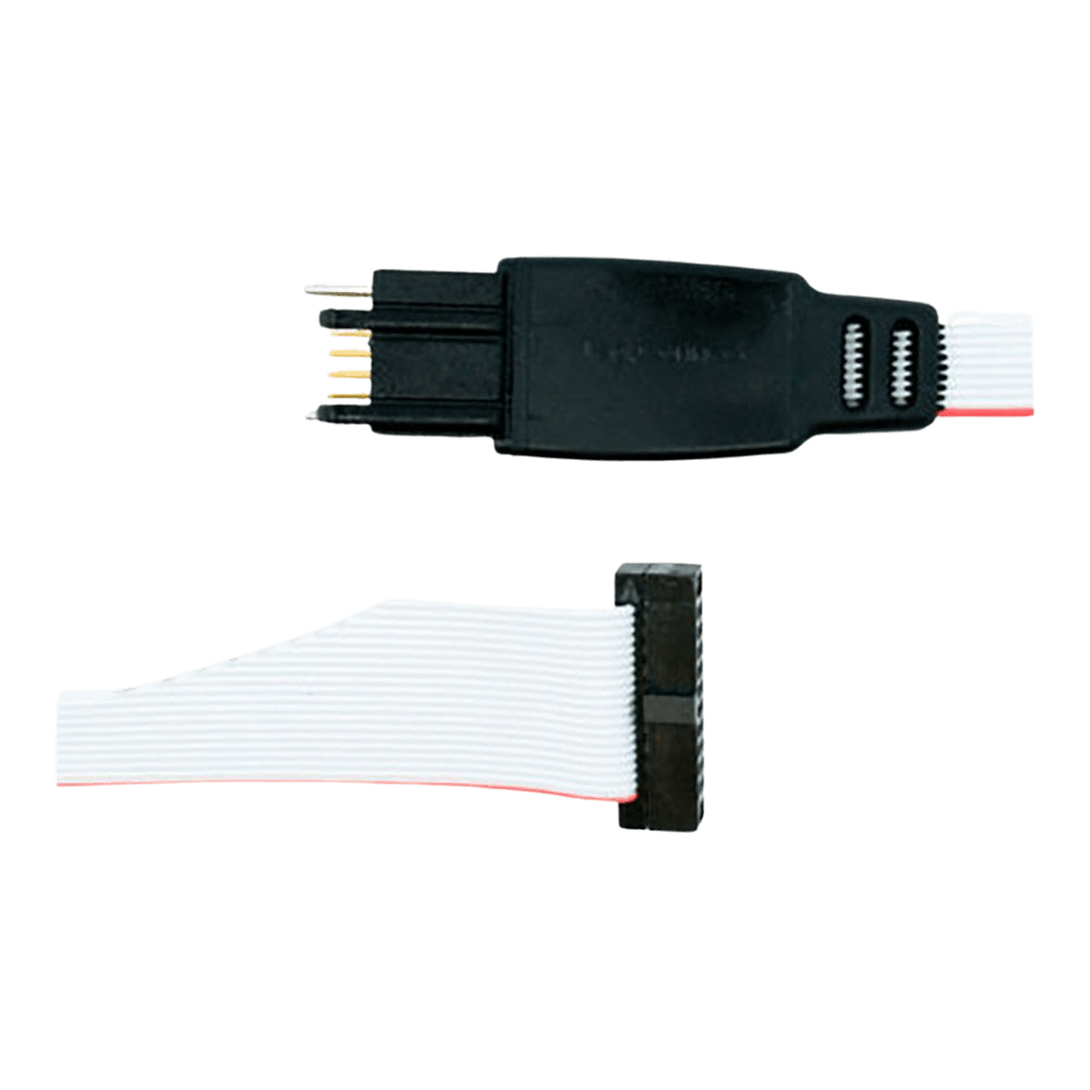
The TC2050 footprint requires precise PCB layout for reliable connection. Contact pads must be 0.079" diameter with 0.100" spacing in a 2x5 configuration. Two 0.079" alignment holes are positioned to ensure correct cable orientation.TC2050 Pinout (Top View): 1 - VTG 2 - TMS/SWDIO 3 - GND 4 - TCK/SWCLK 5 - NC 6 - TDO/SWO 7 - GND 8 - TDI 9 - NC 10 - nRESET * Pins 5 and 9 not connected in standard version ULINK2 Debugger Integration
The cable's 0.050" pitch connector directly mates with ULINK2's Samtec FTSH-105-01 header. This configuration provides efficient debugging for ARM7, ARM9, and Cortex-M microcontrollers with full MDK-ARM integration.PCB Design Considerations
The TC2050 footprint requires careful PCB design attention. Keep-out areas around the connector ensure finger access for cable insertion. The footprint works on both 2-layer and multilayer boards with appropriate via placement.Alternative Configurations
Several variants exist for different debugging requirements: TC2050-IDC-050-ALL: All 10 pins connected for full JTAG compatibility TC2050-IDC-NL-050: No-legs version for production programming TC2050-IDC-050-LEMTA: Reversed connector for Atmel-ICE compatibility| General Information | |
|---|---|
Part Number (SKU) |
TC2050-IDC-050
|
Manufacturer |
|
| Physical and Mechanical | |
Weight |
0.1 kg
|
| Other | |
EAN |
5055383665457
|
Frequently Asked Questions
Have a Question?
-
Can I use this cable for non-ARM microcontrollers?
While designed for ARM Cortex debugging, the cable can carry any signals you design into the footprint. The 10-pin configuration is flexible enough for custom debugging applications on other microcontroller families with appropriate debugger support.
-
What's the maximum target voltage supported?
The cable supports target voltages from 1.2V to 5.5V, covering the full range of modern ARM Cortex microcontrollers. The debugger provides voltage reference sensing through pin 1 of the connector.
-
Is the cable compatible with Atmel-ICE debuggers?
Standard orientation cables work with most debuggers. However, Atmel-ICE has reversed pin numbering, so you'll need the LEMTA (reversed connector) version for proper pin alignment with Atmel debugging tools.
-
How does this compare to traditional debug headers?
Tag Connect cables eliminate the cost and board space of permanent headers. A traditional 10-pin 0.1" header costs more per board and requires significantly more PCB real estate. The TC2050 system provides the same functionality with zero per-board cost.
-
What PCB footprint does this cable require?
The TC2050 footprint requires 10 contact pads and 2 alignment holes. The footprint is significantly smaller than traditional 0.1" pitch headers, typically taking the same space as 2-3 SMT resistors. Full footprint specifications are available in the datasheet.
-
Can I use this cable for production programming?
Yes, the spring pins are rated for over 100,000 connection cycles. However, for high-volume production, consider the no-legs version which offers faster connection times and can be integrated into automated test equipment.
-
What's the difference between legged and no-legs versions?
The legged version (TC2050-IDC-050) includes plastic retention tabs that lock the cable to your PCB for hands-free debugging. The no-legs version (TC2050-IDC-NL-050) has a smaller footprint and connects faster, making it better for automated production programming.
-
Why are pins 5 and 9 not connected in this version?
Pins 5 and 9 are intentionally left unconnected to maintain compatibility with Tag Connect's TC2050-ARM2010 adapter configuration. This follows standard ARM debugging pinout conventions. If you need all 10 pins connected, choose the TC2050-IDC-050-ALL variant.
-
Is this cable compatible with other debuggers besides ULINK2?
Yes, the cable works with any debugger that uses the Samtec FTSH-105-01 style 0.050" pitch 10-pin micro-header. This includes many ARM Cortex debugging tools and development boards with similar connectors.
-
What debugging protocols does the TC2050-IDC-050 support?
The cable supports both JTAG and SWD (Serial Wire Debug) protocols for ARM Cortex microcontrollers. It's particularly optimised for SWD debugging which only requires 2 pins, making it ideal for space-constrained designs.