


Mikroelektronika d.o.o.
Expand 12 Click Board™
Expand 12 Click Board™
SKU: MIKROE-4889
Couldn't load pickup availability
Key Features
Overview
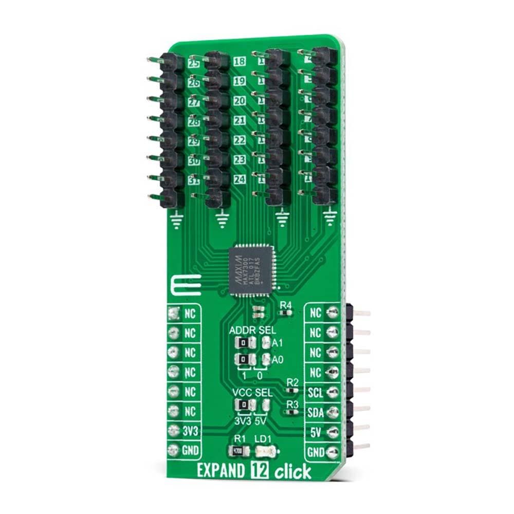
The Expand 12 Click Board™ is a compact add-on board that contains a multi-port I/O expander. This board features the MAX7300, a general-purpose I/O expander providing remote I/O expansion for most MCU’s families from Maxim Integrated, now part of Analog Devices. The MAX7300 comes in a 28-port configuration and allows easy addition of I/O through a standard I2C serial interface. Each port is user-configurable to either a logic input or logic output, capable of sinking 10mA and sourcing 4.5mA. In addition, seven ports feature configurable transition detection logic, which generates an interrupt upon change of port logic level.
The Expand 12 Click Board™ provides a simple solution when additional I/Os are needed while keeping interconnections to a minimum in system monitoring applications, industrial controllers, portable equipment, and many more.
Downloads
How Does The Expand 12 Click Board™ Work?
The Expand 12 Click Board™ as its foundation uses the MAX7300, a general-purpose input/output (GPIO) expander from Maxim Integrated, now part of Analog Devices. This port expander is a simple solution when additional I/Os are needed while keeping interconnections to a minimum, particularly great for system monitoring applications, industrial controllers, portable equipment, and others. The MAX7300 comes in a 28-port configuration, which can be configured to any combination of logic inputs and logic outputs, and default to logic inputs on Power-Up.
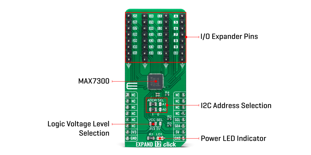
Any I/O port can be configured as a push-pull output (sinking 10mA, sourcing 4.5mA) or a Schmitt-trigger logic input. Each input has an individually selectable internal pull-up resistor. Additionally, transition detection allows seven ports (from port 24 up to port 30) to be monitored in any maskable combination for changes in their logic status. A detected transition is flagged through a status register bit, as well as an interrupt pin (port 31) if desired.
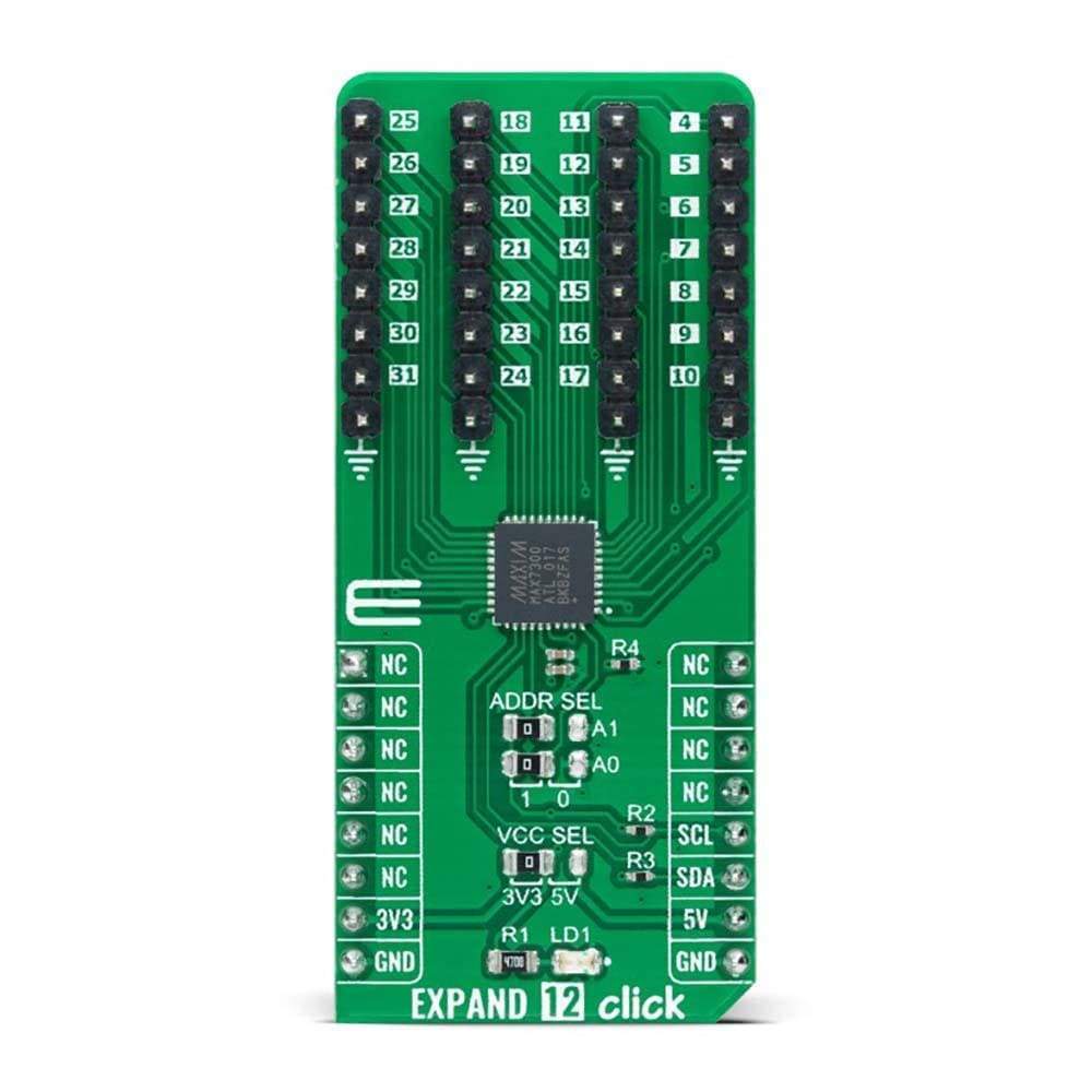
The Expand 12 Click Board™ communicates with MCU using the standard I2C 2-Wire interface to read data and configure settings with a maximum frequency of 400kHz. Besides, it also allows the choice of the least significant bit of its I2C slave address by positioning the SMD jumpers labeled as ADDR SEL to an appropriate position marked as 1 and 0. This way, the MAX7300 provides the opportunity of the 16 possible different I2C addresses by positioning the SMD jumper to an appropriate position.
The Expand 12 Click Board™ can operate with both 3.3V and 5V logic voltage levels selected via the VCC SEL jumper. This way, it is allowed for both 3.3V and 5V capable MCUs to use the I2C communication lines properly. However, the Click board™ comes equipped with a library containing easy-to-use functions and an example code that can be used, as a reference, for further development.
SPECIFICATIONS
| Type | Port expander |
| Applications | Can be used in system monitoring applications, industrial controllers, portable equipment, and many more |
| On-board modules | MAX7300 - general-purpose input/output (GPIO) expander from Maxim Integrated, now part of Analog Devices |
| Key Features | Remote I/O pins that default to inputs at Power-Up, compliant with the I2C-bus Fast and Standard modes, 5V tolerant I/Os, sinking 10mA and sourcing 4.5mA, programmable slave addresses, and more |
| Interface | I2C |
| Compatibility | mikroBUS |
| Click board size | L (57.15 x 25.4 mm) |
| Input Voltage | 3.3V or 5V |
PINOUT DIAGRAM
This table shows how the pinout on the Expand 12 Click Board™ corresponds to the pinout on the mikroBUS™ socket (the latter shown in the two middle columns).
| Notes | Pin | Pin | Notes | ||||
|---|---|---|---|---|---|---|---|
| NC | 1 | AN | PWM | 16 | NC | ||
| NC | 2 | RST | INT | 15 | NC | ||
| NC | 3 | CS | RX | 14 | NC | ||
| NC | 4 | SCK | TX | 13 | NC | ||
| NC | 5 | MISO | SCL | 12 | SCL | I2C Clock | |
| NC | 6 | MOSI | SDA | 11 | SDA | I2C Data | |
| Power Supply | 3.3V | 7 | 3.3V | 5V | 10 | 5V | Power Supply |
| Ground | GND | 8 | GND | GND | 9 | GND | Ground |
ONBOARD SETTINGS AND INDICATORS
| Label | Name | Default | Description |
|---|---|---|---|
| LD1 | PWR | - | Power LED Indicator |
| JP1 | VCC SEL | Left | Logic Level Voltage Selection 3V3/5V: Left position 3V3, Right position 5V |
| JP2-JP3 | ADDR SEL | Left | I2C Address Selection 1/0: Left position 1, Right position 0 |
| J1-J4 | 4-31 | Populated | I/O Expander Ports |
EXPAND 12 CLICK ELECTRICAL SPECIFICATIONS
| Description | Min | Typ | Max | Unit |
|---|---|---|---|---|
| Supply Voltage | 3.3 | - | 5 | V |
| Port Sink Current | - | 10 | - | mA |
| Port Source Current | - | 4.5 | - | mA |
| Number of I/Os | - | - | 28 | pins |
| Operating Temperature Range | -40 | +25 | +125 | °C |
Software Support
We provide a library for the Expand 12 Click Board™ as well as a demo application (example), developed using MikroElektronika compilers. The demo can run on all the main MikroElektronika development boards.
The package can be downloaded/installed directly from NECTO Studio Package Manager (recommended), downloaded from our LibStock™ or found on Mikroe Github account.
Library Description
This library contains API for the Expand 12 Click Board™ driver.
Key functions
-
expand12_set_pin_directionThis function sets the direction of the selected pin. -
expand12_set_pin_valueThis function sets the logic level of the selected pin. -
expand12_read_all_pins_valueThis function reads all pins logic levels.
Example Description
This example demonstrates the use of the Expand 12 Click board™.
 void application_task ( void )
 {
     static uint8_t port_value = 0;
     static uint32_t pins_status = 0;

     expand12_set_port_value( &expand12, EXPAND12_PORT_4_7, EXPAND12_ALL_PINS, port_value );
     expand12_set_port_value( &expand12, EXPAND12_PORT_8_15, EXPAND12_ALL_PINS, port_value );
     expand12_set_port_value( &expand12, EXPAND12_PORT_16_23, EXPAND12_ALL_PINS, port_value++ );

     expand12_read_all_pins_value( &expand12, &pins_status );
     log_printf( &logger, " Pins status (32-bit) : 0x%.8LXrnn", pins_status );
     Delay_ms( 100 );
 }
The full application code, and ready to use projects can be installed directly from NECTO Studio Package Manager (recommended), downloaded from our LibStock™ or found on Mikroe Github account.
Other Mikroe Libraries used in the example:
- MikroSDK.Board
- MikroSDK.Log
- Click.Expand12
Additional Notes and Information
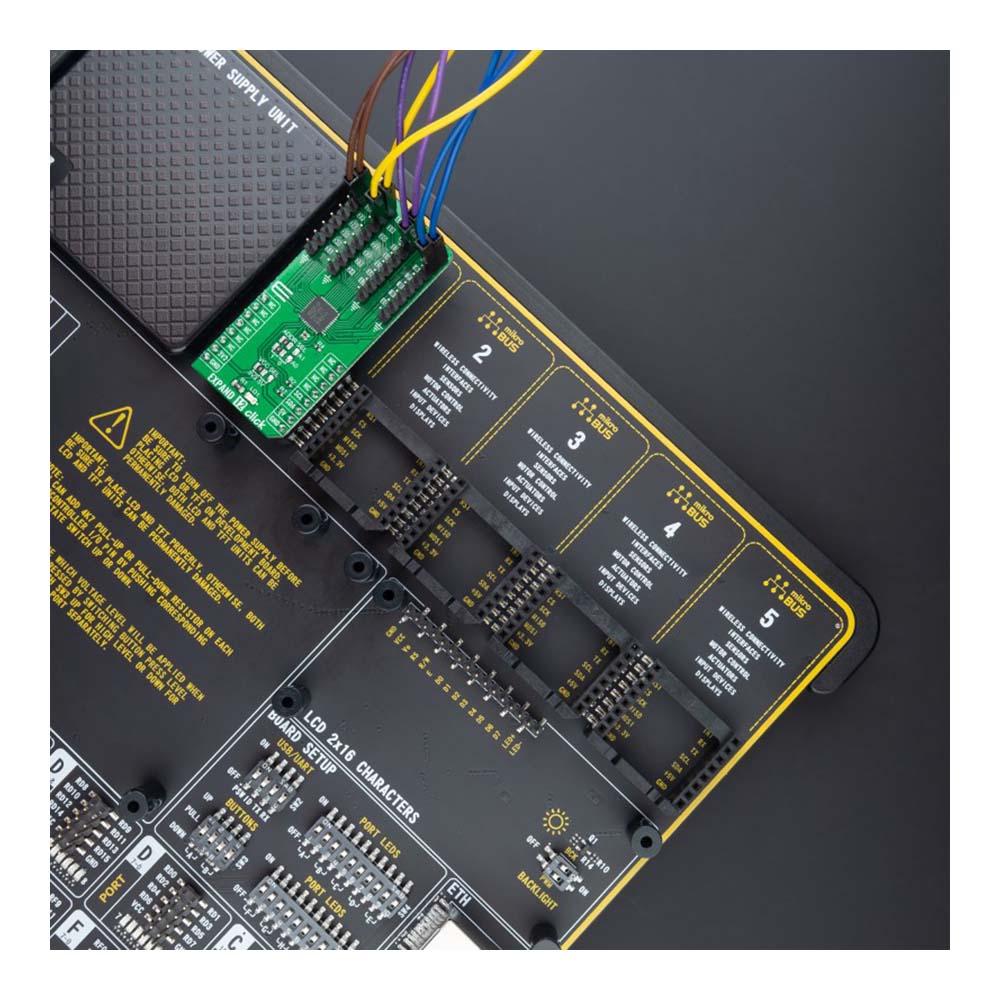
Depending on the development board you are using, you may need a USB UART click, USB UART 2 Click or RS232 Click to connect to your PC, for development systems with no UART to USB interface available on the board. UART terminal is available in all MikroElektronika compilers.
MIKROSDK
TheExpand 12 Click Board™ is supported with mikroSDK - MikroElektronika Software Development Kit. To ensure proper operation of mikroSDK compliant Click board™ demo applications, mikroSDK should be downloaded from the LibStock and installed for the compiler you are using.
| General Information | |
|---|---|
Part Number (SKU) |
MIKROE-4889
|
Manufacturer |
|
| Physical and Mechanical | |
Weight |
0.02 kg
|
| Other | |
EAN |
8606027384332
|
Frequently Asked Questions
Have a Question?
Be the first to ask a question about this.