


Mikroelektronika d.o.o.
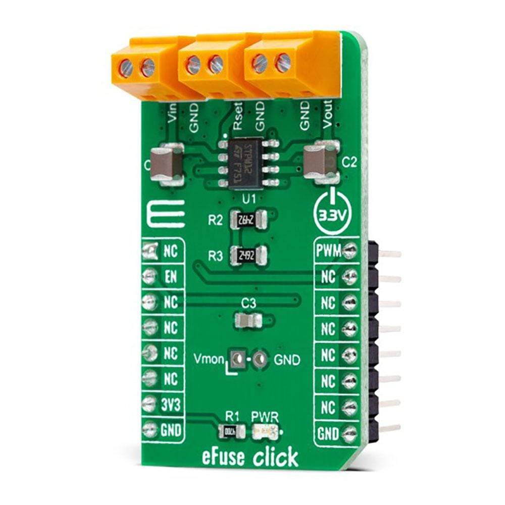
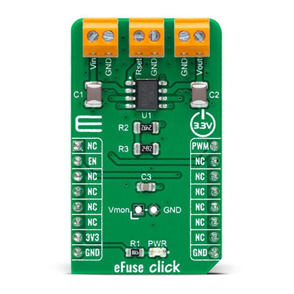
eFuse Click Board™
eFuse Click Board™
SKU: MIKROE-4726
Couldn't load pickup availability
Overview
The eFuse Click Board™ is a compact add-on board that contains a programmable electronic power breaker. This board features the STPW12, an integrated electronic power breaker optimized to monitor the input power from STMicroelectronics. Connected in series to the power rail, it can disconnect the electronic circuitry on its output if the power consumption overcomes the programmed limit. The intervention of the protection is communicated to the MCU through a signal on the fault pin. The device can also be enabled/disabled through a dedicated Enable pin with a direct PWM mode, which can be achieved through an external PWM signal.
The eFuse Click Board™ is suitable for industrial and consumer applications, fault protection, overcurrent surge protection, and more
Downloads
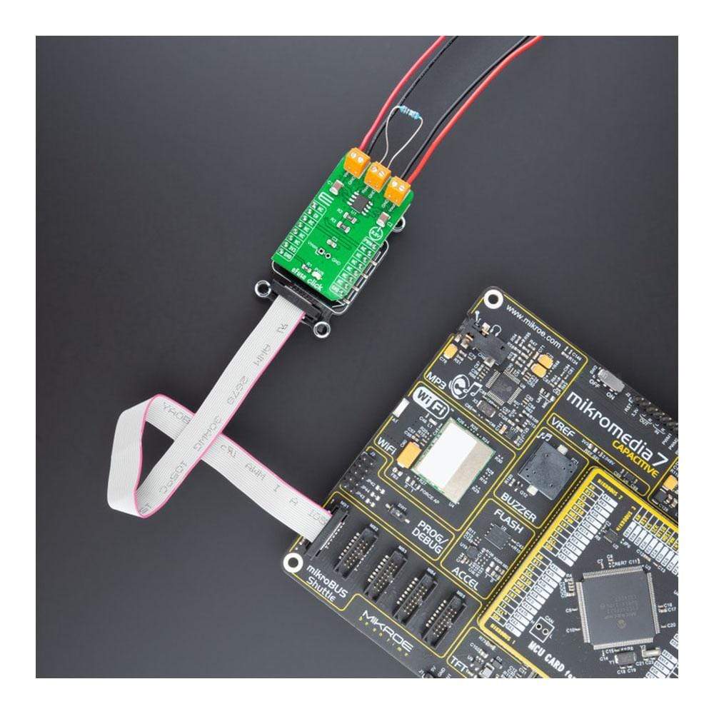
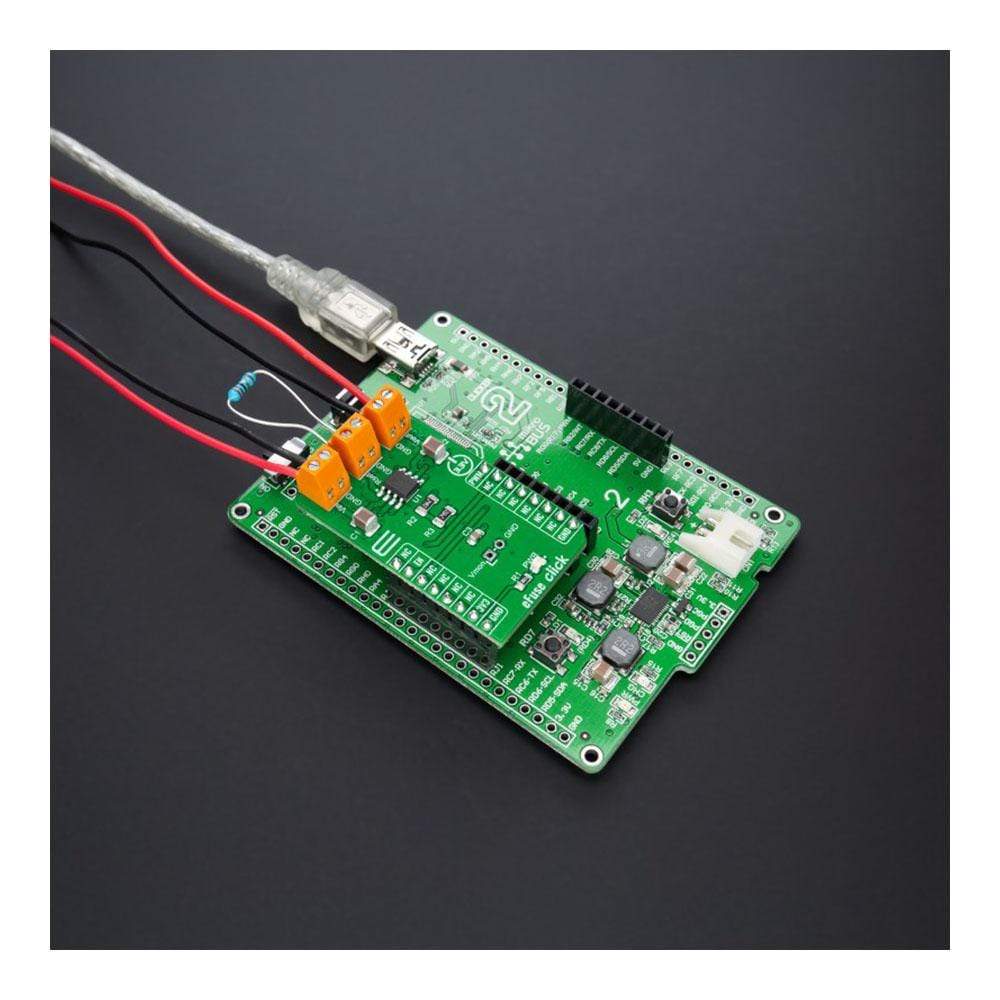
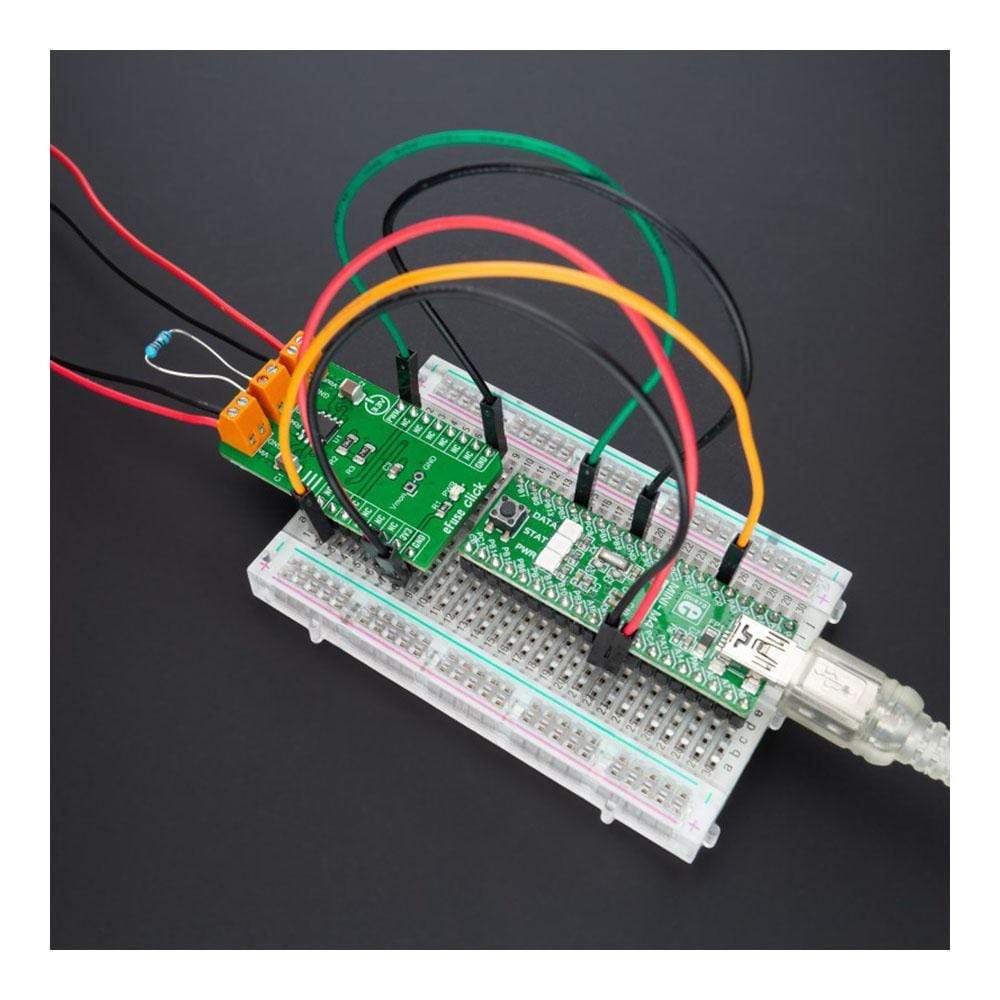
How Does The eFuse Click Board™ Work?
The eFuse Click Board™ as its foundation uses the STPW12, a programmable electronic power breaker optimized to monitor the input power from STMicroelectronics. The device is designed and optimized to work on 12V power rails, even if the operating supply voltage can range from 10.5V to 18V. Connected in series to the power rail, it can disconnect the electronic circuitry on its output if the power consumption overcomes the programmed limit. The intervention threshold is programmed by the resistor connected by the RSET terminal. When this happens, the STPW12 automatically opens the integrated power switch and disconnects the load.
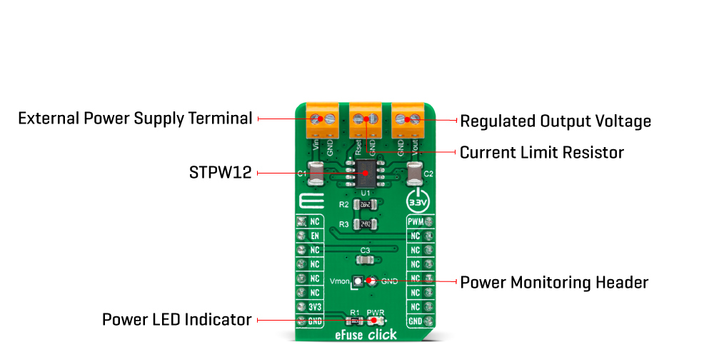
The overcoming of the power limit threshold is signaled on the monitor/fault pin on the onboard header pin labelled as VMON. The monitor/fault pin is proportional to the power, continuously present on the pin, and provides two valuable signals for the real-time control of the device and application status. After a particular delay time, programmable by the user, the STPW12 automatically tries again to close the internal switch and re-connect the load.
The eFuse Click Board™ communicates with MCU using two GPIO pins routed on the PWM and RST pins of the mikroBUS™ socket labelled PWM and EN. The device can be enabled or disabled through a dedicated Enable (EN) pin with a direct PWM mode, which can be achieved through an external PWM signal. In this mode, the device's internal power switch can be driven ON/OFF by an external PWM signal, provided to the PWM pin of the STPW12 (square wave, maximum 2kHz, duty cycle 20% - 100%). This approach allows the user to optimize the design power distribution system in terms of accurate power control, choice of isolation material, safety improvements, such as the reduced risk of flammability and easier qualification and certification flow.
The eFuse Click Board™ can be operated only with a 3.3V logic voltage level. The board must perform appropriate logic voltage level conversion before use with MCUs with different logic levels. However, the Click board™ comes equipped with a library containing functions and an example code that can be used, as a reference, for further development.
SPECIFICATIONS
| Type | Power Switch |
| Applications | The eFuse Click Board™ can be used for industrial and consumer applications, fault protection, overcurrent surge protection, and more |
| On-board modules | STPW12 - programmable electronic power breaker optimized to monitor the input power from STMicroelectronics |
| Key Features | Real-time input power sensing, undervoltage lockout, PWM mode, thermal shutdown, enable function, short-circuit current limit, and more |
| Interface | GPIO,PWM |
| Compatibility | mikroBUS |
| Click board size | M (42.9 x 25.4 mm) |
| Input Voltage | 3.3V,External |
PINOUT DIAGRAM
This table shows how the pinout of the eFuse Click Board™ corresponds to the pinout on the mikroBUS™ socket (the latter shown in the two middle columns).
| Notes | Pin | Pin | Notes | ||||
|---|---|---|---|---|---|---|---|
| NC | 1 | AN | PWM | 16 | PWM | PWM Signal | |
| Enable | EN | 2 | RST | INT | 15 | NC | |
| NC | 3 | CS | RX | 14 | NC | ||
| NC | 4 | SCK | TX | 13 | NC | ||
| NC | 5 | MISO | SCL | 12 | NC | ||
| NC | 6 | MOSI | SDA | 11 | NC | ||
| Power Supply | 3.3V | 7 | 3.3V | 5V | 10 | NC | |
| Ground | GND | 8 | GND | GND | 9 | GND | Ground |
ONBOARD SETTINGS AND INDICATORS
| Label | Name | Default | Description |
|---|---|---|---|
| LD1 | PWR | - | Power LED Indicator |
| J1 | VMON | Unpopulated | Power Monitoring Header |
EFUSE CLICK ELECTRICAL SPECIFICATIONS
| Description | Min | Typ | Max | Unit |
|---|---|---|---|---|
| Supply Voltage VCC | - | 3.3 | - | V |
| External Supply Voltage VIN | 10.5 | 12 | 18 | V |
| Current Limit | - | 1 | - | A |
| Power Limit Range | 10 | - | 15 | W |
| PWM Signal Frequency | - | 2 | - | kHz |
| PWM Duty Cycle | 20 | - | 100 | % |
| Operating Temperature Range | -40 | +25 | +125 | °C |
| General Information | |
|---|---|
Part Number (SKU) |
MIKROE-4726
|
Manufacturer |
|
| Physical and Mechanical | |
Weight |
0.02 kg
|
| Other | |
EAN |
8606027383311
|
Frequently Asked Questions
Have a Question?
Be the first to ask a question about this.