Overview
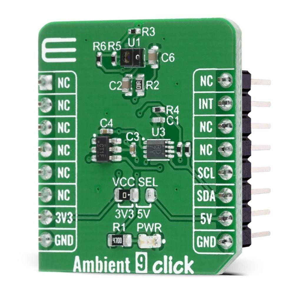
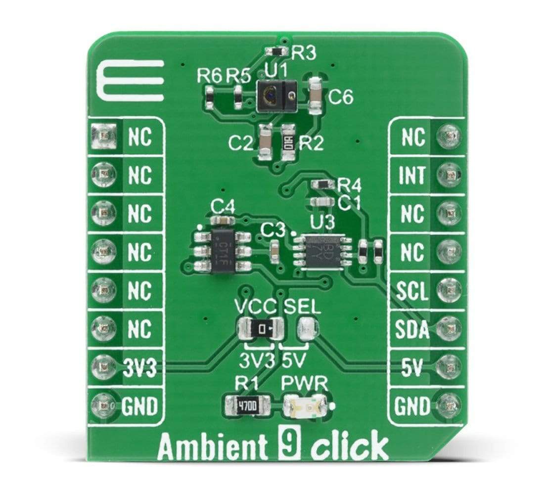
The Ambient 9 Click Board™ is a compact add-on board that contains an integrated ambient light sensing and proximity detector with IR LED in an optical module. This board features the APDS-9160-003, digital ALS, and IR sensing, an IR LED, and a complete proximity sensing solution from Broadcom Limited, that is fit to be used under a small aperture of the device's window cover. It has a wide dynamic range, the proximity detection feature operates well from bright sunlight to dark rooms, and both the PS and ALS functions independently provides maximum flexibility in applications. The Ambient 9 Click Board™ is suitable for display management to extend battery life and provide optimum viewing in diverse lighting conditions.
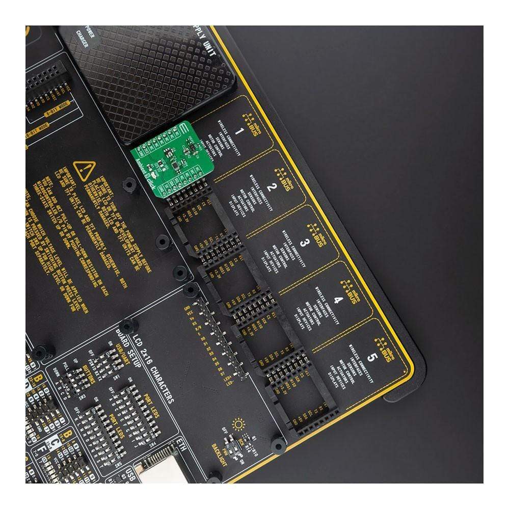
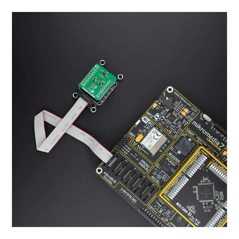
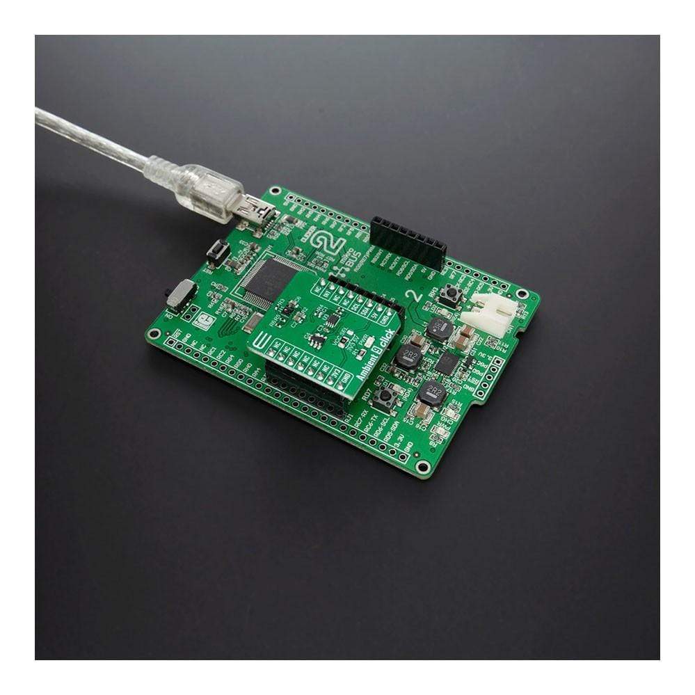
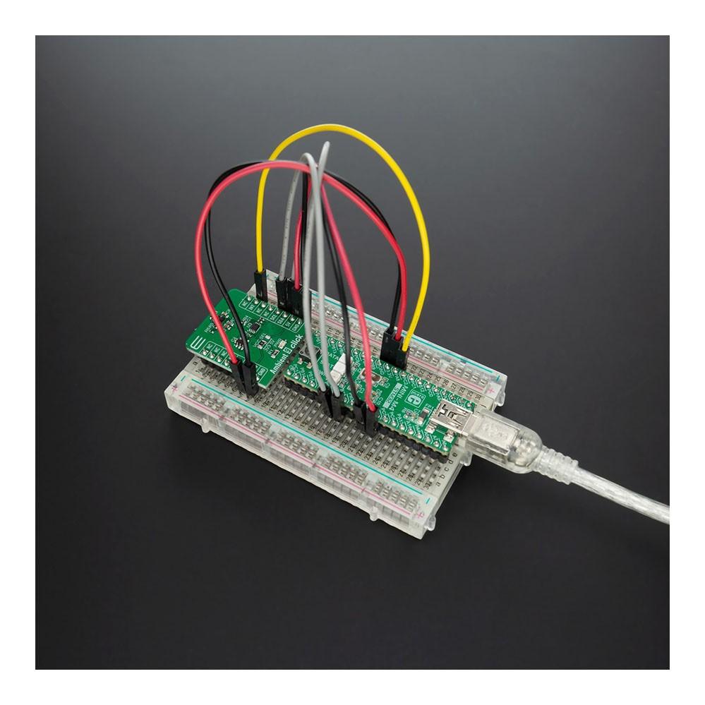
The Ambient 9 Click Board™ is supported by a mikroSDK compliant library, which includes functions that simplify software development. This Click Board™ comes as a fully tested product, ready to be used on a system equipped with the mikroBUS™ socket.
Downloads
How Does The Ambient 9 Click Board™ Work?
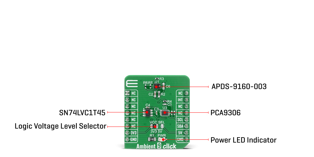
The Ambient 9 Click Board™ is based on the APDS-9160-003, digital proximity, and ambient light sensing sensor from Broadcom Limited. The ambient light sensor provides a photopic response to light intensity in low light conditions or behind a darkened glass. It approximates the response of the human eye providing a direct readout where the output count is proportional to the ambient light level. The proximity detection also operates well from bright sunlight to dark rooms. Additionally, the device can be put into a low-power standby mode providing a very low average power consumption.
In a proximity sensing system, the included IR LED can be pulsed with more than 100 mA of rapidly switching current. The number of LED pulses can be configured by using the pulse step, and the LED modulation frequency can be set from 60 kHz to 100 kHz in 5 steps. Proximity sensing resolution can vary from 8 to 11 bits, and the measurement rate can vary from 6.25 ms to 400 ms. This Click board™ is easy to program and read data because it does not require an overly demanding configuration. In order to read ambient or proximity data, it is only necessary to enable certain registers which can also be seen in an example code that contains easy to use functions that may be used as a reference for further development.
The Ambient 9 Click Board™ communicates with the MCU using the standard I2C 2-wire interface. Standard (100 kHz) and Fast (400 kHz) I2C communication modes are available with the device. The I2C bus lines are routed to the dual bidirectional PCA9306 voltage-level translator from Texas Instruments, which allows interfacing with both 3.3V and 5V MCUs. It also generates flexible ambient and proximity programmable interrupt signals routed on the INT pin of the mikroBUS™, which are triggered if upper or lower threshold values are crossed. It is also possible to deactivate a sensor after a certain interrupt event occurred.
The Ambient 9 Click Board™ is designed to be operated with both 3.3V and 5V logic levels that can be selected via a VCC SEL jumper. This allows for both 3.3V and 5V capable MCUs to use the I2C communication lines properly.
SPECIFICATIONS
| Type | Optical |
| Applications | Can be used for display management to extend battery life and provide optimum viewing in diverse lighting conditions. |
| On-board modules | Ambient 9 Click is based on the APDS-9160-003, digital proximity, and ambient light sensing sensor from Broadcom Limited. |
| Key Features | Low power consumption, high precision, programmable interrupt, high sensitivity in low lux condition, and more. |
| Interface | I2C |
| Compatibility | mikroBUS |
| Click board size | S (28.6 x 25.4 mm) |
| Input Voltage | 3.3V or 5V |
PINOUT DIAGRAM
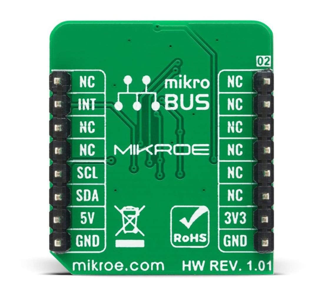
This table shows how the pinout on the Ambient 9 Click Board™ corresponds to the pinout on the mikroBUS™ socket (the latter shown in the two middle columns).
| Notes | Pin |  |
Pin | Notes | |||
|---|---|---|---|---|---|---|---|
| NC | 1 | AN | PWM | 16 | NC | ||
| NC | 2 | RST | INT | 15 | INT | Interrupt | |
| NC | 3 | CS | RX | 14 | NC | ||
| NC | 4 | SCK | TX | 13 | NC | ||
| NC | 5 | MISO | SCL | 12 | SCL | I2C Clock | |
| NC | 6 | MOSI | SDA | 11 | SDA | I2C Data | |
| Power Supply | 3.3V | 7 | 3.3V | 5V | 10 | 5V | Power Supply |
| Ground | GND | 8 | GND | GND | 9 | GND | Ground |
ONBOARD SETTINGS AND INDICATORS
| Label | Name | Default | Description |
|---|---|---|---|
| LD1 | PWR | - | Power LED Indicator |
| JP1 | VCC SEL | Left | Power Supply Voltage Selection 3V3/5V: Left position 3V3, Right position 5V |
AMBIENT 9 CLICK ELECTRICAL SPECIFICATIONS
| Description | Min | Typ | Max | Unit |
|---|---|---|---|---|
| Supply Voltage | - | - | 3.63 | V |
| Peak Wavelength | - | 940 | - | nm |
| Output Resolution | - | 18 | - | bit |
| Operating Temperature Range | -40 | - | +85 | °C |
| General Information | |
|---|---|
Part Number (SKU) |
MIKROE-4197
|
Manufacturer |
|
| Physical and Mechanical | |
Weight |
0.018 kg
|
| Other | |
Country of Origin |
|
HS Code Customs Tariff code
|
|
EAN |
8606027380303
|
Warranty |
|
Frequently Asked Questions
Have a Question?
Be the first to ask a question about this.


