Overview
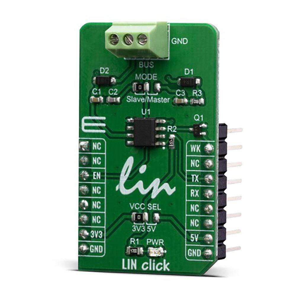
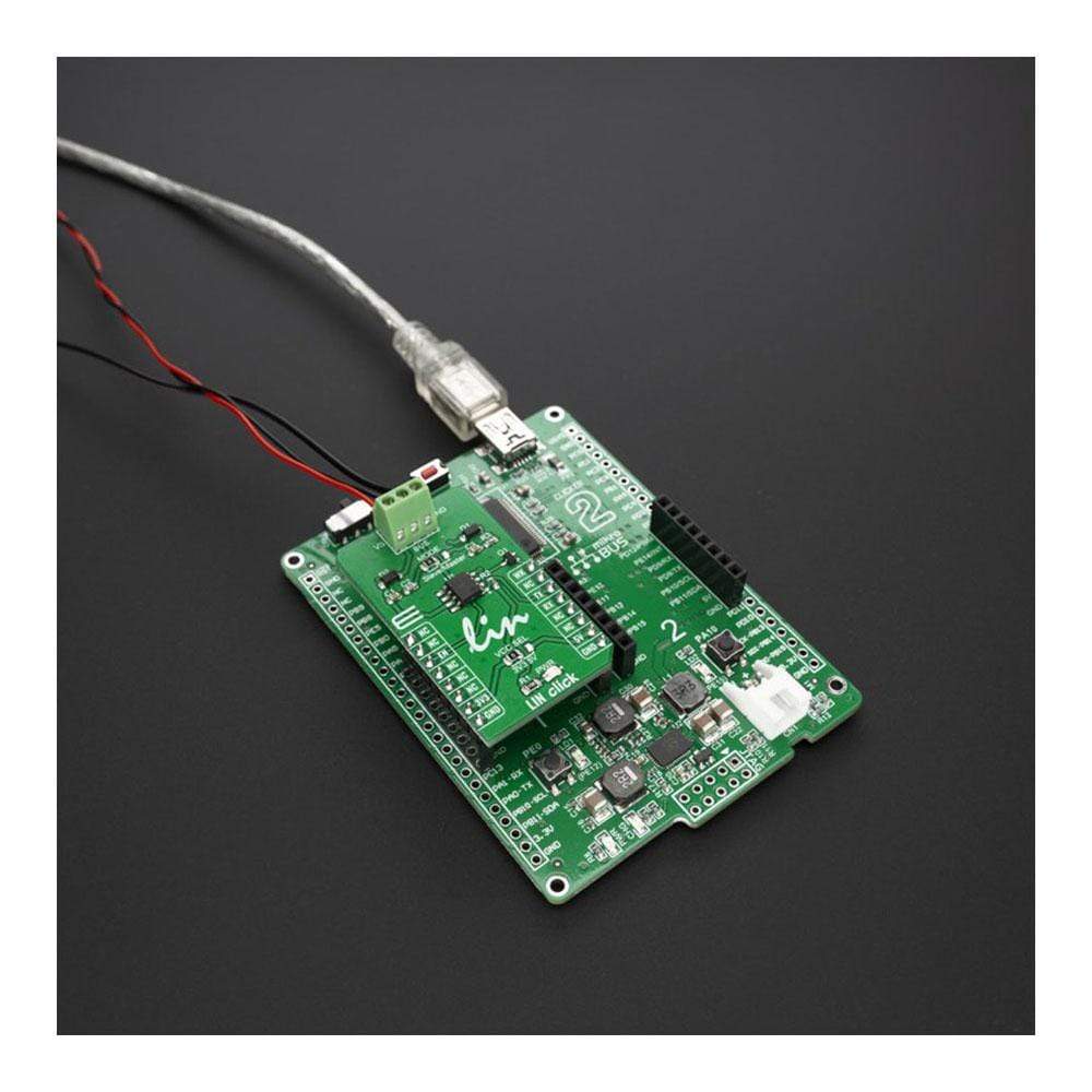
The LIN Click Board™ features the TLE7259-3GE, a LIN transceiver from Infineon Technologies, with integrated wake-up and protection features. The combination of Slave and Master node in LIN systems, the LIN Click Board™ can be used for automotive applications: body controllers and gateway modules, switch panels, wiper or window lift modules, door and seat control modules and engine management units.
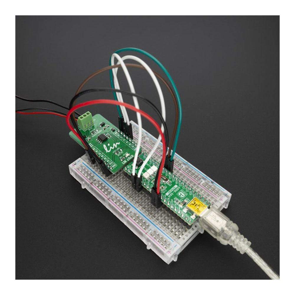
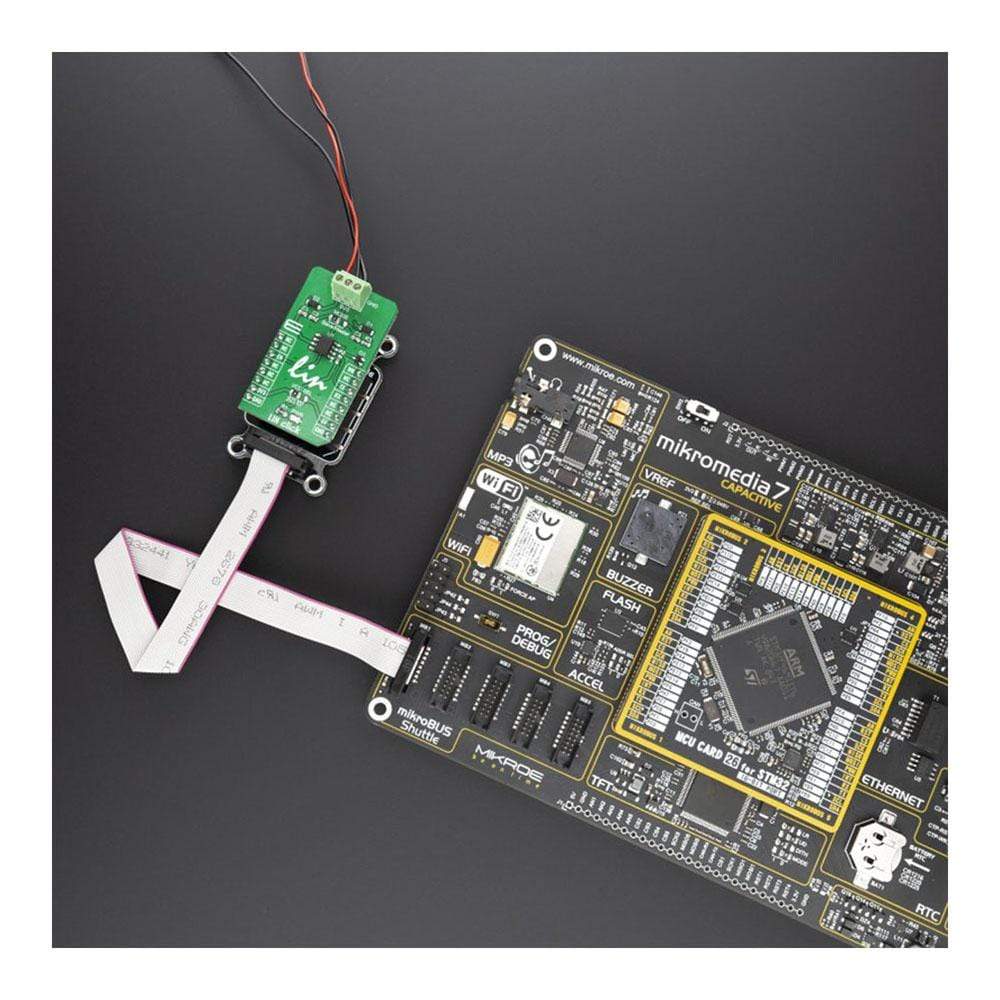
The LIN Click Board™ is supported by a mikroSDK compliant library, which includes functions that simplify software development. This Click Board™ comes as a fully tested product, ready to be used on a system equipped with the mikroBUS™ socket.
Downloads
How Does The LIN Click Board™ Work?
LIN or Local Interconnect Network is a protocol used for communicating between components in vehicles. These days cars have hundreds of sensor applications to measure things like temperature, pressure, air flow, speed, etc. All these applications need to communicate with the main system. The LIN Click Board™ is based on the TLE7259-3GE, LIN transceiver from Infineon Technologies with integrated wake-up and protection features. It is designed for in-vehicle networks using data transmission and it operates as a bus driver between the protocol controller and the physical bus of the LIN network. Compliant to all LIN standards and with a wide operational supply range the TLE7259-3GE can be used in all automotive applications. It can be used with CAN (Controller Area Network), but LIN is more cost-effective for simple sensor networks in vehicles.
.jpg)
In Sleep-mode the TLE7259-3GE draws typically less than 8 μA of quiescent current while still being able to wake up when detecting LIN bus traffic and a local wake up signals. The very low leakage current on the BUS pin makes the TLE7259-3 especially suitable for partially supplied networks. Based on the Infineon Smart Power Technology SPT®, the TLE7259-3GE provides excellent ESD Robustness and a very high electromagnetic compliance (EMC). The TLE7259-3GE reaches very low levels of electromagnetic emission within a broad frequency range, independent from the battery voltage. The TLE7259-3GE and the Infineon SPT® technology are AEC qualified and tailored to withstand the harsh condition of the automotive environment.
The LIN Click Board™ can be configure for master node applications or for slave node applications, every LIN network consists of a master node and one or more slave nodes. The LIN click communicates with the MCU by using the UART RX and TX signals. RX and TX signals are also routed to the header on the edge of the click board™ so they can be used independently of the mikroBUS™ socket. Its most important features are the fact that it is a single-wire LIN transceiver for transmission rates up to 20 kbps and it is compliant to ISO 17987-4 and LIN Specification 2.2A. It has a very low current consumption in sleep mode with wake-up functions and it is digital I/O levels compatible with 3.3 V and 5 V microcontrollers. It is optimized for high electromagnetic compatibility (EMC); Very low emission and high immunity to interference.
The TLE7259-3GE has 3 major operation modes:
- Stand-By mode
- Normal Operation mode
- Sleep mode
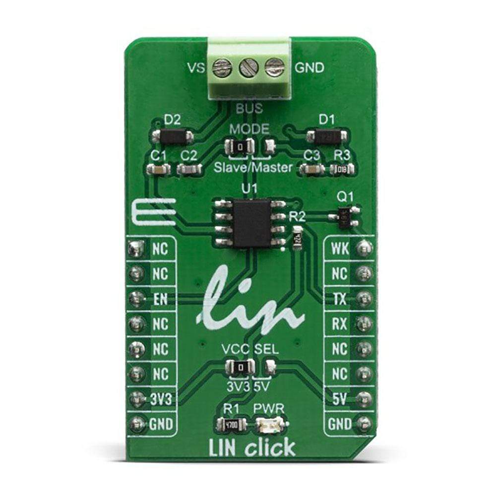
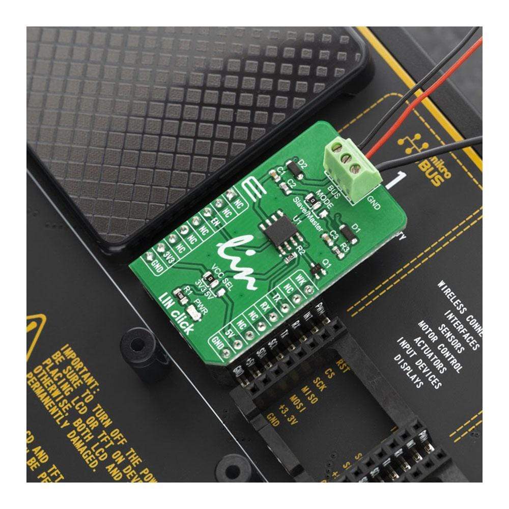
The LIN Click Board™ has a Terminal Block connector for LIN communication, LIN bus power supply Vs, LIN bus input / output data line and LIN bus ground GND .
The LIN Click Board™, due to its key features and on-board modules, can be used for various automotive applications including body controllers and gateway modules, switch panels, wiper or window lift modules, door and seat control modules and engine management units.
SPECIFICATIONS
| Type | LIN |
| Applications | Automotive applications: Body controllers and gateway modules, switch panels, wiper or window lift modules, door and seat control modules and engine management units |
| On-board modules | TLE7259-3GE LIN transceiver from Infineon Technologies |
| Key Features | Data rates up to 20kBaud, Low electromagnetic emission, Very low current consumption in sleep mode (8µA) |
| Interface | GPIO,UART |
| Compatibility | mikroBUS |
| Click board size | M (42.9 x 25.4 mm) |
| Input Voltage | 3.3V or 5V |
PINOUT DIAGRAM
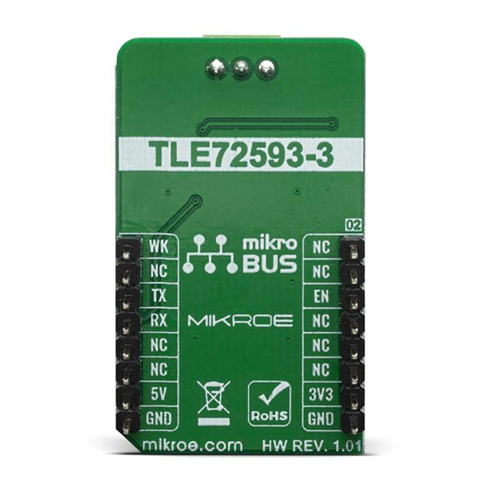
This table shows how the pinout of the LIN Click Board™ corresponds to the pinout on the mikroBUS™ socket (the latter shown in the two middle columns).
| Notes | Pin |  |
Pin | Notes | |||
|---|---|---|---|---|---|---|---|
| NC | 1 | AN | PWM | 16 | WK | Wake Up | |
| NC | 2 | RST | INT | 15 | NC | ||
| Output Enable | EN | 3 | CS | RX | 14 | TX | UART Transmit |
| NC | 4 | SCK | TX | 13 | RX | UART Receive | |
| NC | 5 | MISO | SCL | 12 | NC | ||
| NC | 6 | MOSI | SDA | 11 | NC | ||
| Power Supply | 3.3V | 7 | 3.3V | 5V | 10 | 5V | Power Supply |
| Ground | GND | 8 | GND | GND | 9 | GND | Ground |
ONBOARD SETTINGS AND INDICATORS
| Label | Name | Default | Description |
|---|---|---|---|
| JP1 | VCC SEL | Left | Power supply voltage selection: left position 3.3V, right position 5V |
| JP2 | MODE | Left | Communication MODE selection: left position is Slave mode, right position is Master mode |
| LD1 | PWR | - | Power LED indicator |
| CN1 | LIN | - | Screw terminal for connecting LIN bus |
| General Information | |
|---|---|
Part Number (SKU) |
MIKROE-3816
|
Manufacturer |
|
| Physical and Mechanical | |
Weight |
0.018 kg
|
| Other | |
Country of Origin |
|
HS Code Customs Tariff code
|
|
EAN |
8606018719730
|
Warranty |
|
Frequently Asked Questions
Have a Question?
Be the first to ask a question about this.


