Buck-Boost Click Board
Overview
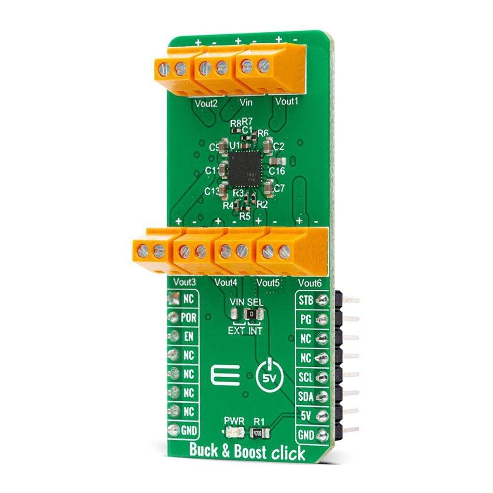
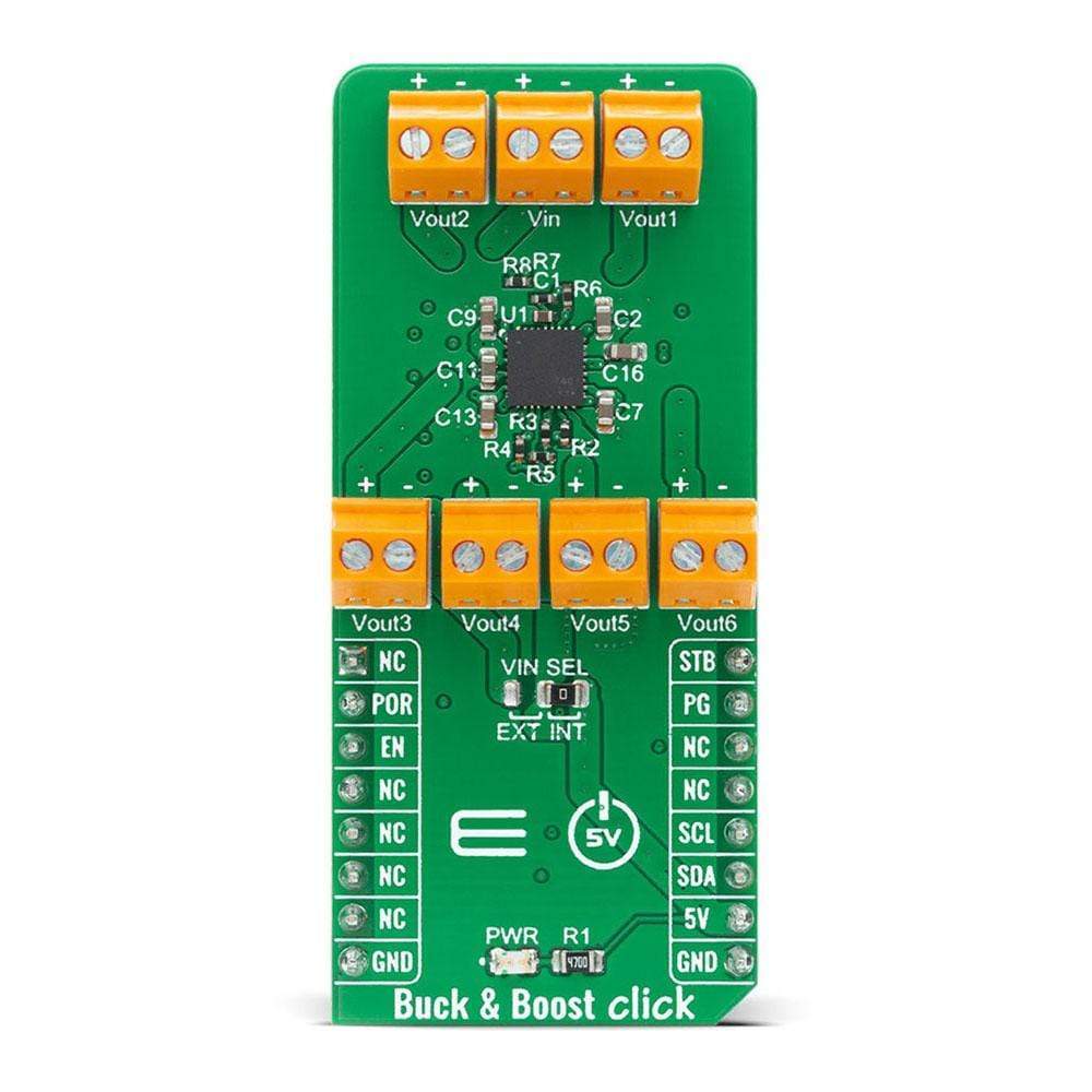
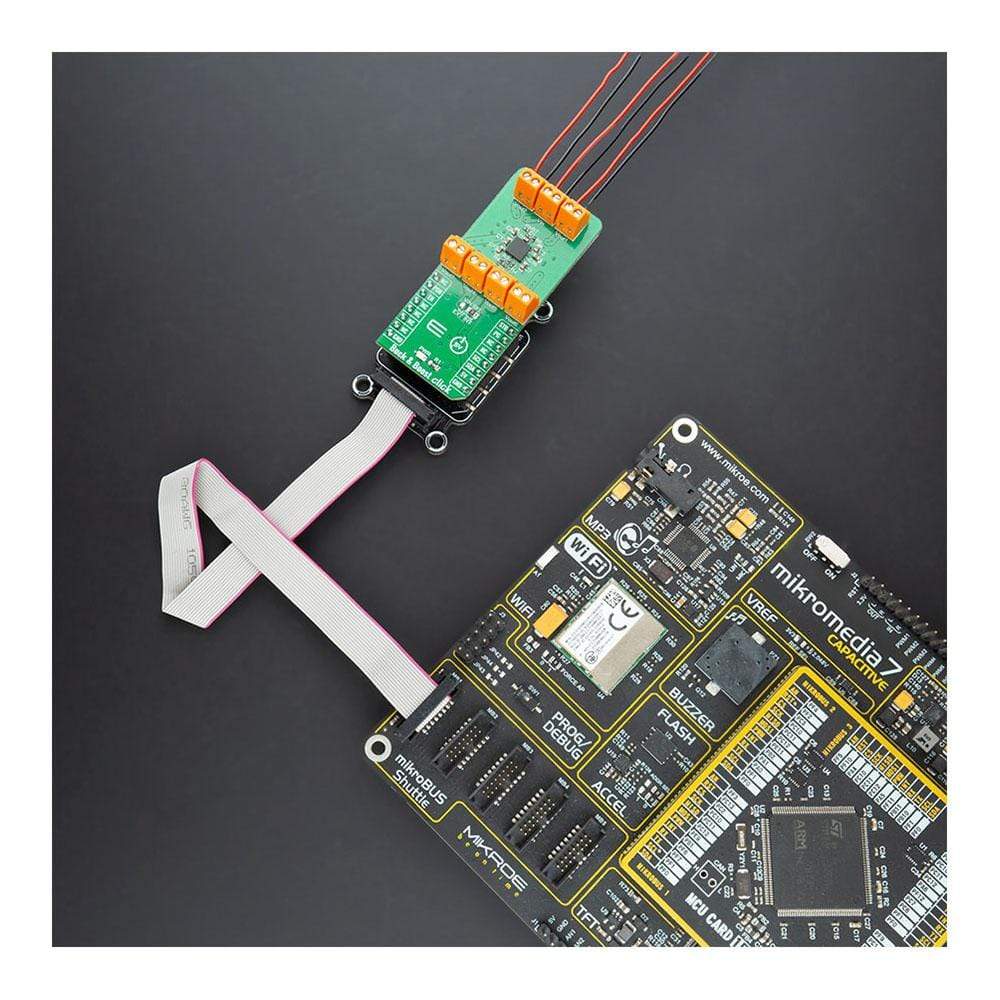
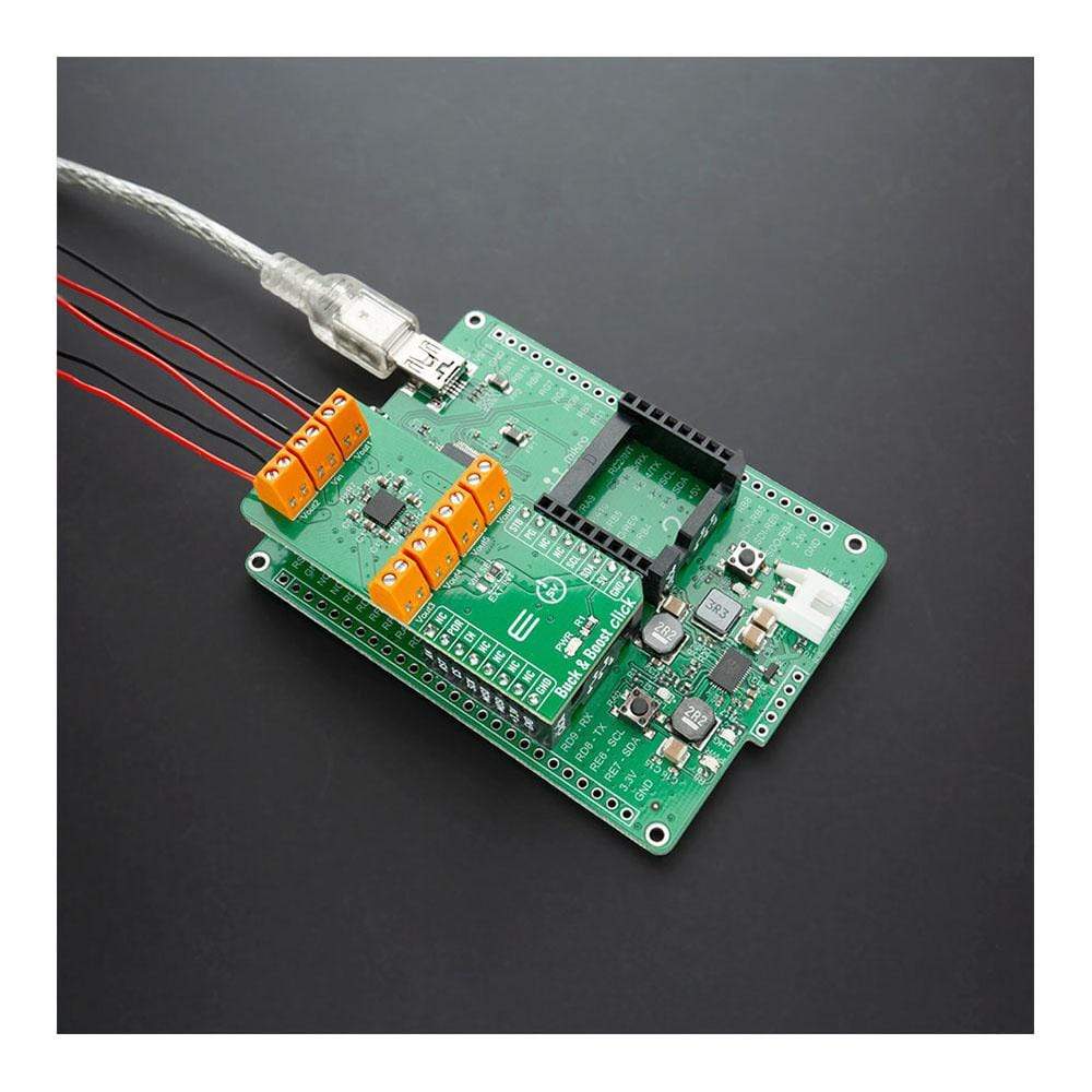
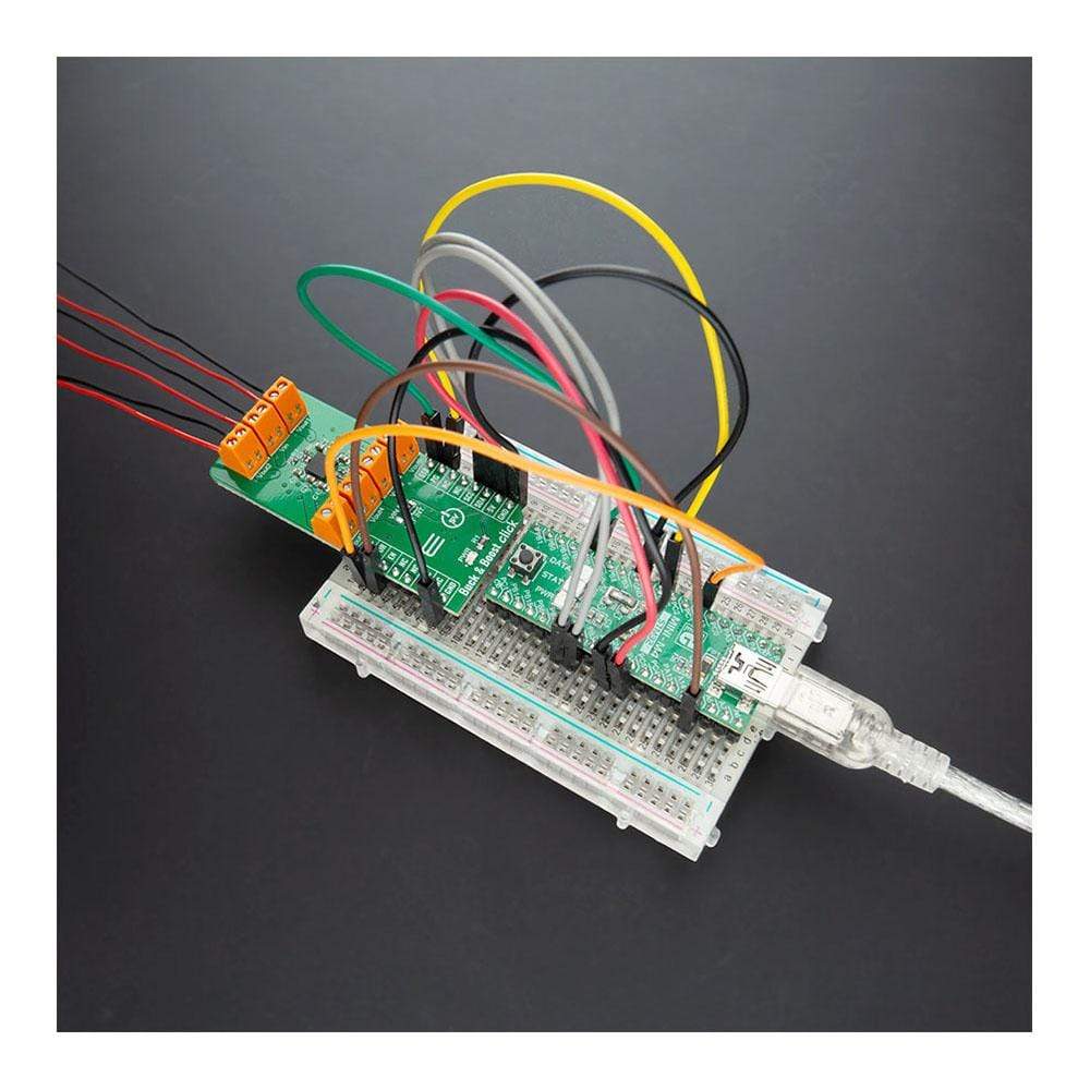
The Buck-Boost Click Board™ is a high-efficiency buck-boost DC/DC converter. It features the Linear Technology' LTC3129-1, a buck-boost DC/DC conversion integrated circuit. The Click Board™ supports a wide input voltage range and can output eight discrete regulated output voltage levels, selectable by the digital output voltage selection pins, ranging from 2.5V to 15V. The main features of this converter are its very low noise and low ripple at the output, as well as very high regulating efficiency and low quiescent current.
Those features make the Buck-Boost Click Board™ a perfect solution for the regulators and post-regulators for harvested energy, solar panel post-regulators/chargers, rechargeable battery output voltage regulators, wireless low noise applications and similar.
How Does The Buck-Boost Click Board™ Work?
The Buck-Boost Click Board™ is based on the LTC3129-1, a 1.3μA quiescent current, monolithic, current mode, buck-boost DC/DC converter that can operate over a wide input voltage range of 1.92V to 15V and provide up to 200mA to the load from Analog Devices. The LTC3129-1 is characterized by its very low noise and low ripple level at the output, as well as very high regulating efficiency and low quiescent current. Eight fixed, user-programmable output voltages can be selected using the three digital programming pins routed to the INT, AN, and CS pin of the mikroBUS™ socket. A proprietary switch control algorithm allows the Buck-Boost converter to maintain output voltage regulation with input voltages that are above, below, or equal to the output voltage. Transitions between the step-up or step-down operating modes are seamless and free of transients and sub-harmonic switching, making this product ideal for noise-sensitive applications.
The Buck-Boost Click Board™ possesses two different modes of operation - PWM and Burst Mode, depending on the nature of the application. The PWM mode can be selected by setting the PWM pin of the mikroBUS™ socket to a logic high level and is suitable for working with higher loads connected to the converter output and when the extremely low output noise is required. When the PWM mode is selected, LTC3129-1 has a fixed nominal switching frequency of 1.2MHz using an internally compensated average current mode control loop. In this mode, the ripple and the noise level of the output voltage are minimal.
For high-efficiency operation at light loads, automatic Burst Mode operation can be selected, reducing the quiescent current down to 1.3µA. Burst mode can be chosen if the PWM pin is set to a logic low level. If the connected load is light enough, the converter will remain working in Burst mode, running only when necessary to maintain voltage regulation. Otherwise, the PWM mode will be automatically engaged, providing enough current for the connected load.
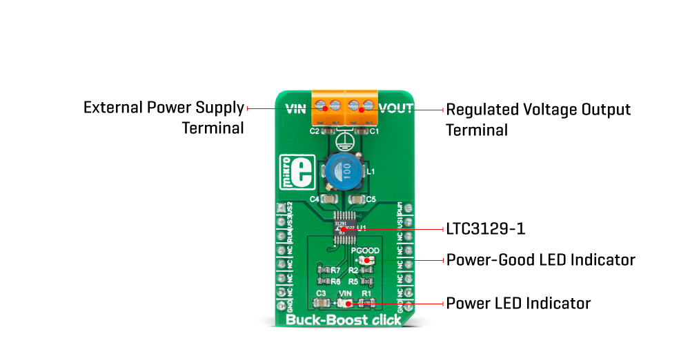
The Buck-Boost Click Board™ completely powers itself from the VIN external power supply terminal. Once the power is applied to the VIN terminal, the circuit also has to be enabled by setting the RUN pin routed to the RST pin of the mikroBUS™ socket to a high logic level. This will power up the converter, which will be indicated by the PWR LED indicator. It also includes additional features such as a power-good output with a Power Good LED indicator labelled as PGOOD that pulls to the ground when FB drops too far below its regulated voltage. This pin also can sink up to the absolute maximum rating of 15mA when set low.
VOLTAGE SELECTION PINS SETTINGS
VS3 / CS | VS2 / AN | VS1 / INT | VOUT |
---|---|---|---|
0 | 0 | 0 | 2.5V |
0 | 0 | 1 | 3.3V |
0 | 1 | 0 | 4.1V |
0 | 1 | 1 | 5.0V |
1 | 0 | 0 | 6.9V |
1 | 0 | 1 | 8.2V |
1 | 1 | 0 | 12V |
1 | 1 | 1 | 15V |
SPECIFICATIONS
Type | Buck-Boost |
Applications | The Buck-Boost Click Board™ can be used for the regulators and post-regulators for harvested energy, solar panel post-regulators/chargers, rechargeable battery output voltage regulators, wireless low noise applications, and similar. |
On-board modules | The Buck-Boost Click Board™ is based on the LTC3129-1, a 1.3μA quiescent current, monolithic, current mode, buck-boost DC/DC converter that can operate over a wide input voltage range of 1.92V to 15V and provide up to 200mA to the load from Analog Devices. |
Key Features | Fixed output voltage with eight user-selectable settings, Power-Good Indicator, very low noise and low ripple at the output, as well as very high regulating efficiency and low quiescent current, and more. |
Interface | GPIO,PWM |
Compatibility | mikroBUS |
Click board size | M (42.9 x 25.4 mm) |
Input Voltage | External |
PINOUT DIAGRAM
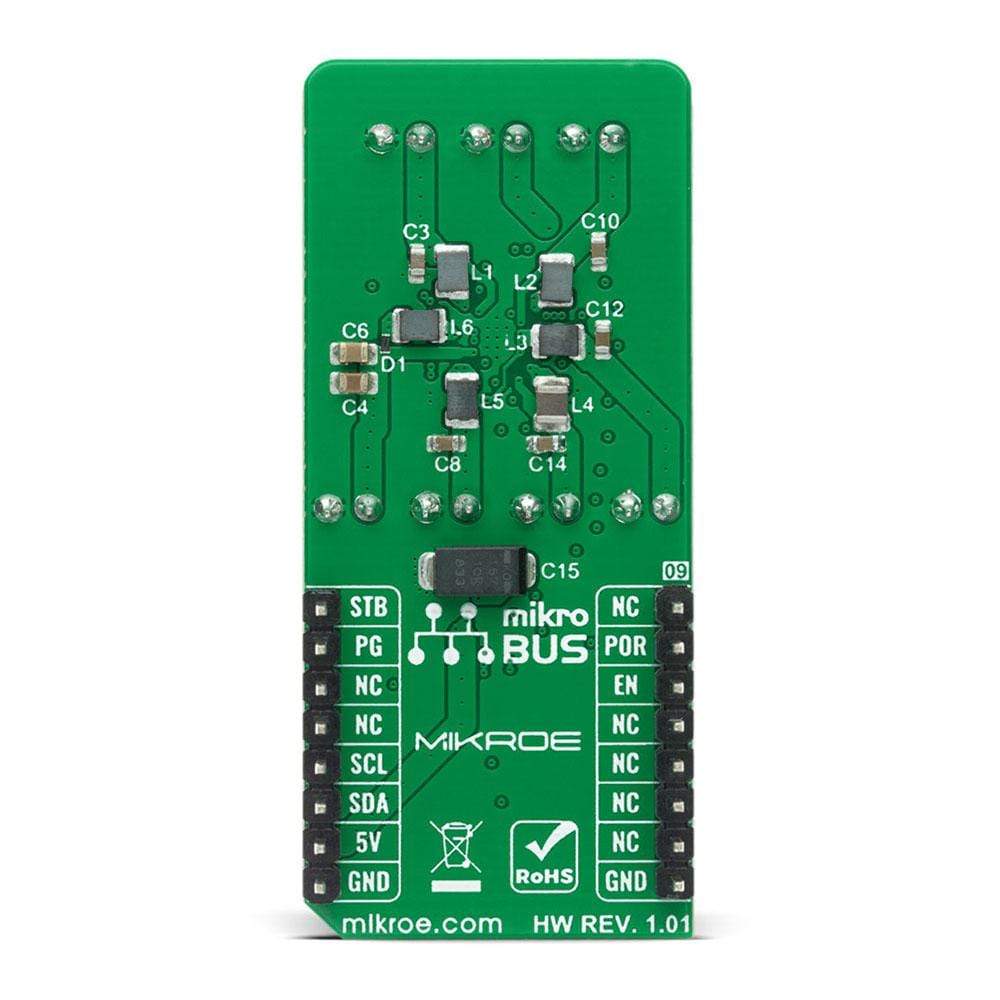
This table shows how the pinout of the Buck-Boost Click Board™ corresponds to the pinout on the mikroBUS™ socket (the latter shown in the two middle columns).
Notes | Pin | Pin | Notes | ||||
---|---|---|---|---|---|---|---|
Output voltage select pin | VS2 | 1 | AN | PWM | 16 | PWM | Mode select pin |
Enable pin | RUN | 2 | RST | INT | 15 | VS1 | Output voltage select pin |
Output voltage select pin | VS3 | 3 | CS | RX | 14 | NC | |
NC | 4 | SCK | TX | 13 | NC | ||
NC | 5 | MISO | SCL | 12 | NC | ||
NC | 6 | MOSI | SDA | 11 | NC | ||
NC | 7 | 3.3V | 5V | 10 | NC | ||
Ground | GND | 8 | GND | GND | 9 | GND | Ground |
ONBOARD SETTINGS AND INDICATORS
Label | Name | Default | Description |
---|---|---|---|
LD1 | VIN | - | Power LED Indicator |
LD2 | PGOOD | - | Power-Good LED Indicator |
BUCK-BOOST CLICK ELECTRICAL SPECIFICATIONS
Description | Min | Typ | Max | Unit |
---|---|---|---|---|
Input voltage range (VIN) | 1.92 | 15 | V | |
Output voltage range (VOUT) | 2.425 | 15.50 | V | |
Inductor average current limit | 80 | 200 | 350 | mA |
Operating Temperature Range | -40 | - | +125 | °C |
Software Support
We provide a library for the Buck-Boost Click Board™ on our LibStock page, as well as a demo application (example), developed using MikroElektronika compilers. The demo can run on all the main MikroElektronika development boards.
Library Description
The library covers all the necessary functions to control the Buck-Boost Click Board™. This library contains drivers for set the output value of 2500 mV, 3300 mV, 4100 mV, 5000 mV, 6900 mV, 8200 mV, 12000 mV and 15000 mV to the converter LTC3129-1 on Buck Boost Click.
Key Functions
void buckboost_defaultConfig()
- Set default configuration functionvoid buckboost_set2500mV()
- Set the output voltage of 2500 mV functionvoid buckboost_set15000mV()
- Set the output voltage of 15000 mV function
Example Description
The application is composed of three sections :
- System Initialization - Initializes GPIO and AN, RST, CS, PWM and INT pins as output.
- Application Initialization - Initialization driver enable's - GPIO, set default configuration and start write log.
- Application Task - (code snippet) This is a example which demonstrates the use of the Buck-Boost Click Board™. Change output voltage from 2500 mV to 15000 mV every 5 seconds. All data logs write on USB UART for approximately once every 5 sec.
void applicationTask() { mikrobus_logWrite( " Set Output Voltage of 2500 mV ", _LOG_LINE ); mikrobus_logWrite( "--------------------------------", _LOG_LINE ); buckboost_set2500mV(); Delay_ms( 5000 ); mikrobus_logWrite( " Set Output Voltage of 3300 mV ", _LOG_LINE ); mikrobus_logWrite( "--------------------------------", _LOG_LINE ); buckboost_set3300mV(); Delay_ms( 5000 ); mikrobus_logWrite( " Set Output Voltage of 4100 mV ", _LOG_LINE ); mikrobus_logWrite( "--------------------------------", _LOG_LINE ); buckboost_set4100mV(); Delay_ms( 5000 ); mikrobus_logWrite( " Set Output Voltage of 5000 mV ", _LOG_LINE ); mikrobus_logWrite( "--------------------------------", _LOG_LINE ); buckboost_set5000mV(); Delay_ms( 5000 ); mikrobus_logWrite( " Set Output Voltage of 6900 mV ", _LOG_LINE ); mikrobus_logWrite( "--------------------------------", _LOG_LINE ); buckboost_set6900mV(); Delay_ms( 5000 ); mikrobus_logWrite( " Set Output Voltage of 8200 mV ", _LOG_LINE ); mikrobus_logWrite( "--------------------------------", _LOG_LINE ); buckboost_set8200mV(); Delay_ms( 5000 ); mikrobus_logWrite( " Set Output Voltage of 12000 mV ", _LOG_LINE ); mikrobus_logWrite( "--------------------------------", _LOG_LINE ); buckboost_set12000mV(); Delay_ms( 5000 ); mikrobus_logWrite( " Set Output Voltage of 15000 mV ", _LOG_LINE ); mikrobus_logWrite( "--------------------------------", _LOG_LINE ); buckboost_set15000mV(); Delay_ms( 5000 ); }
The full application code, and ready to use projects can be found on our LibStock page.
Other mikroE Libraries used in the example:
- GPIO
Additional Notes and Information
Depending on the development board you are using, you may need USB UART click, USB UART 2 click or RS232 click to connect to your PC, for development systems with no UART to USB interface available on the board. The terminal available in all MikroElektronika compilers, or any other terminal application of your choice, can be used to read the message.
MIKROSDK
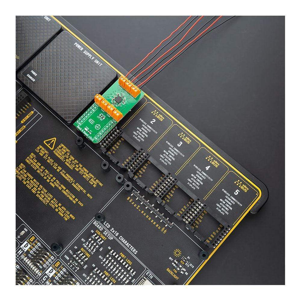
The Buck-Boost Click Board™ is supported with mikroSDK - MikroElektronika Software Development Kit. To ensure proper operation of mikroSDK compliant Click board™ demo applications, mikroSDK should be downloaded from the LibStock and installed for the compiler you are using.
Frequently Asked Questions
Have a Question?
Be the first to ask a question about this.