


Mikroelektronika d.o.o.
UVC Click Board™
UVC Click Board™
SKU: MIKROE-4144
Couldn't load pickup availability


Overview
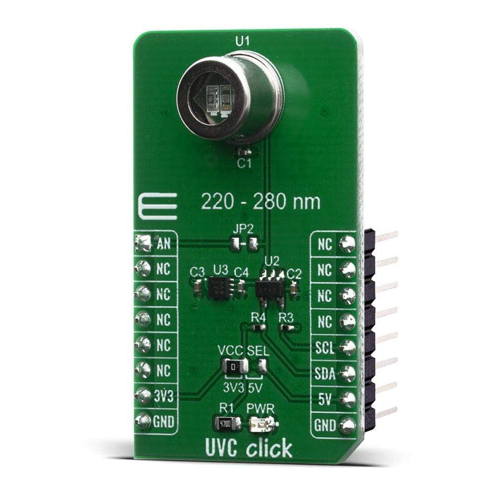
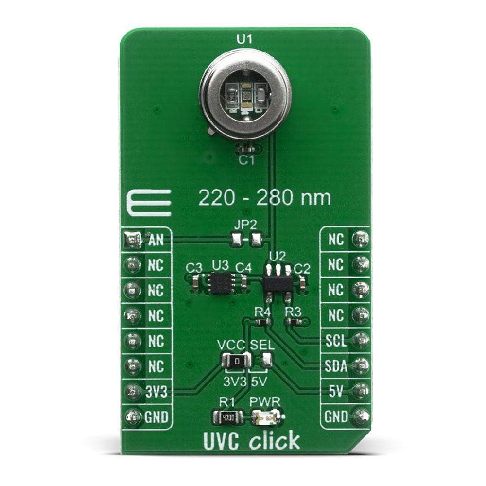
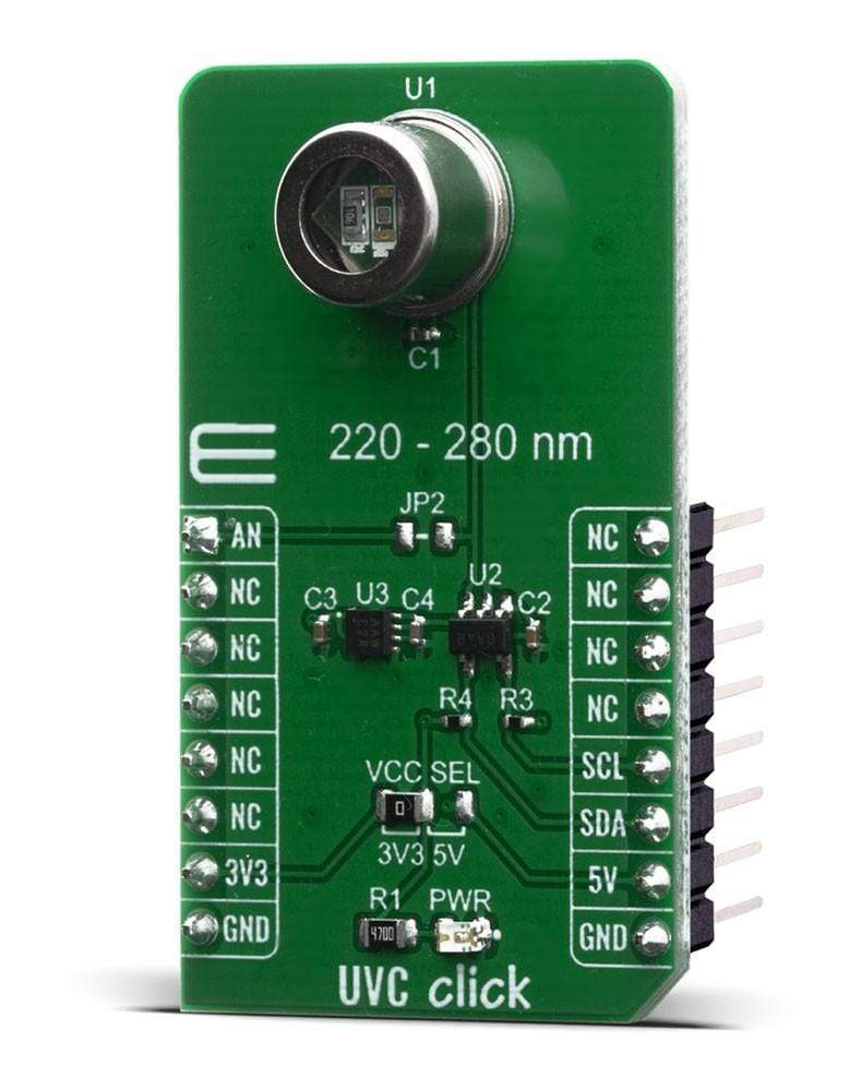
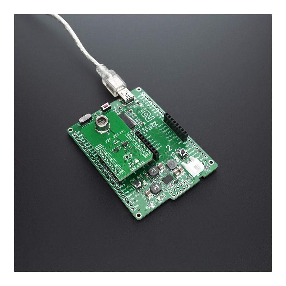
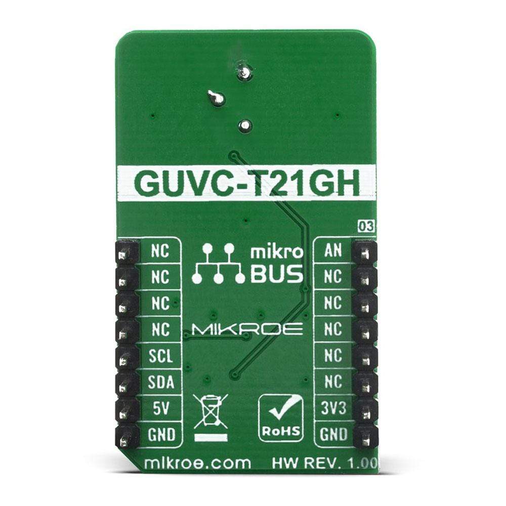
The UVC Click Board™ is an ultraviolet sensing board that complements UVC Light Click Board™ for an ultimate ultraviolet solution. The board is based on a GUVC-T21GH ultraviolet sensor from GenUV, capable of measuring UVC spectrum in the range of 220nm up to 280nm and light intensity from 0mW/cm² up to 9.3mW/cm².
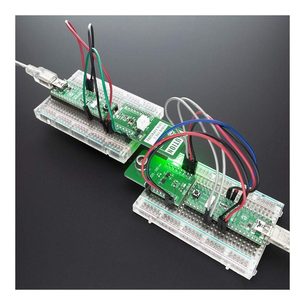
With high sensitivity and good solar blindness, it can be a perfect solution for monitoring sterilisation lamps used in ultraviolet germicidal irradiation (UVGI), a disinfection method that is becoming an essential tool in the battle against viruses and bacteria.
The UVC Click Board™ has two ways of reading UV sensor output, direct analogue output value and digital output thanks to the MCP3221 ADC converter.
Downloads
How Does The UVC Click Board™ Work?
The UVC Click Board™ can provide reliable and stable UVC light intensity value by using GUVC-T21GH sensor which have spectral detection range of 220nm - 280nm with output responsivity of 0.6mV/nW (at 254nm). Light intensity is converted in digital value by using MCP3221 a successive approximation A/D converter (ADC) with a 12-bit resolution.
.jpg)
Communication to the MCP3221 is performed using a 2-wire, I2C compatible interface. Standard (100 kHz) and Fast (400 kHz) I2C modes are available with the device. An on-chip conversion clock enables independent timing for the I2C and conversion clocks.
To get reliable readings from sensor, ADC power and voltage reference is supplied from MCP1501T-33E/RW a buffered voltage reference with 3.3V output capable of sourcing up to 20mA of current as a low-drift bandgap-based reference. The bandgap uses chopper-based amplifiers, effectively reducing the drift to zero.
Second way of reading output voltage from sensor is by placing 0 ohm resistor on JP2 position labeled on PCB and reading analog value from AN pin on mikroBUS™. This way you can relay on external voltage reference and ADC with some other desired specifications for your application and you can measure light power intensity up to 14.1 mW/cm².
An SMD jumper labeled as VCC SEL can be moved to the desired position, allowing both 3.3V and 5V MCUs to be used with the UVC Click Board™.
SPECIFICATIONS
| Type | Optical,UVC Light |
| Applications | The UVC Click Board™ can be used for UV measurement applications, sterilization lamp monitoring, prototyping of wearables, handsets, and various consumer electronics based on received UV light |
| On-board modules | GUVC-T21GH |
| Key Features | UVC sensing with 12-bit resolution, High Sensitivity, Good Solar Blindness |
| Interface | Analog,I2C |
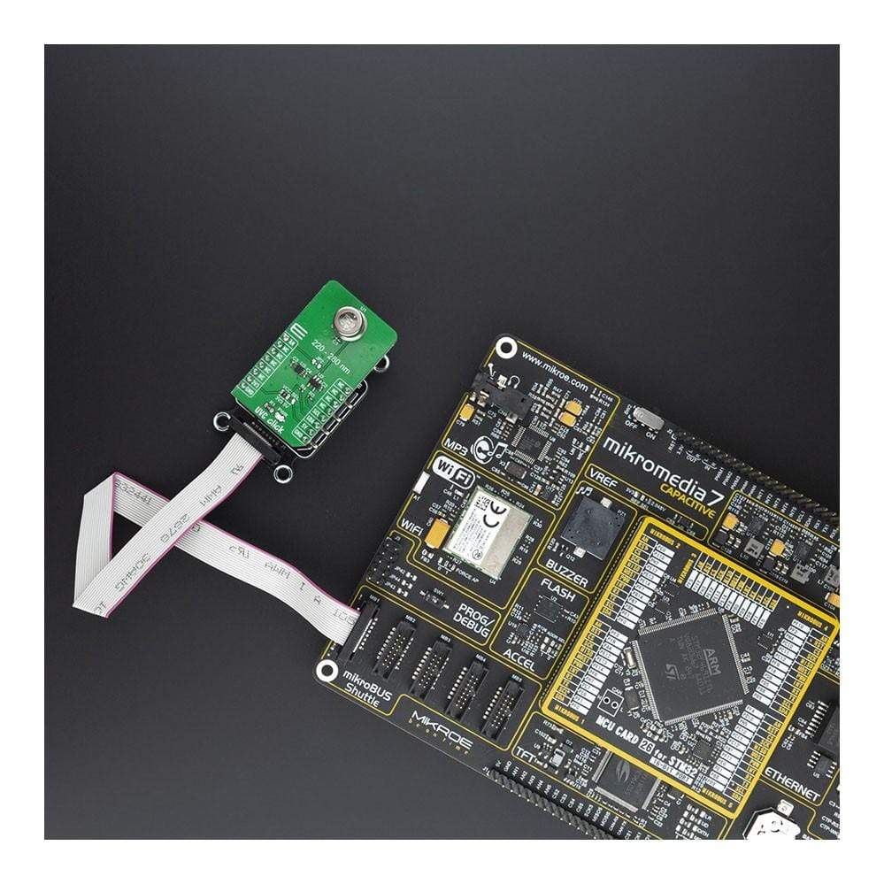
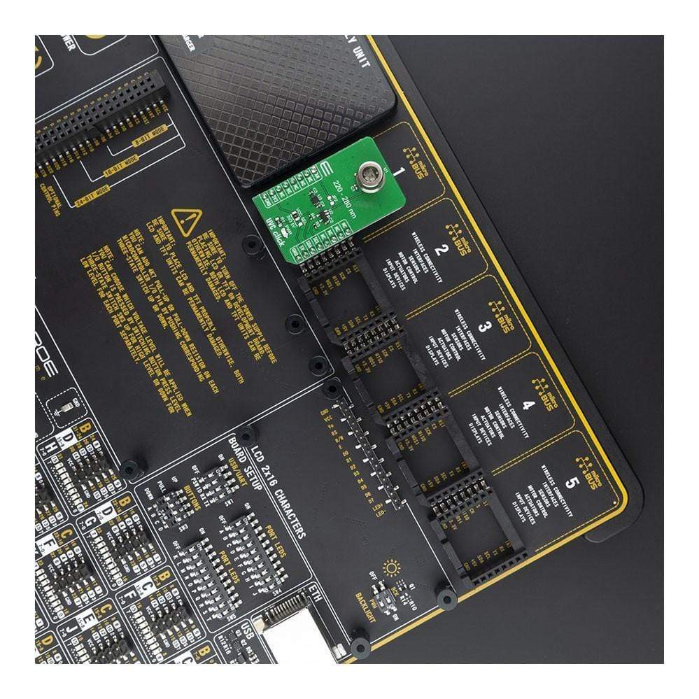
| Compatibility | mikroBUS |
| Click board size | M (42.9 x 25.4 mm) |
| Input Voltage | 3.3V or 5V |
PINOUT DIAGRAM
This table shows how the pinout on the UVC Click Board™ corresponds to the pinout on the mikroBUS™ socket (the latter shown in the two middle columns).
| Notes | Pin | Pin | Notes | ||||
|---|---|---|---|---|---|---|---|
| Analog Voltage Output | AN | 1 | AN | PWM | 16 | NC | |
| NC | 2 | RST | INT | 15 | NC | ||
| NC | 3 | CS | RX | 14 | NC | ||
| NC | 4 | SCK | TX | 13 | NC | ||
| NC | 5 | MISO | SCL | 12 | SCL | I2C Clock | |
| NC | 6 | MOSI | SDA | 11 | SDA | I2C Data | |
| Power Supply | 3.3V | 7 | 3.3V | 5V | 10 | 5V | Power Supply |
| Ground | GND | 8 | GND | GND | 9 | GND | Ground |
ONBOARD SETTINGS AND INDICATORS
| Label | Name | Default | Description |
|---|---|---|---|
| PWR | LD1 | - | Power LED Indicator |
| VCC SEL | JP1 | Left | Logic level voltage selection: left position 3V3, right position 5V |
| JP2 | Jumper | NP | Jumper for direct analog voltage reading from sensor |
TECHNICAL SPECIFICATION
| Characteristic | Value |
|---|---|
| UVC sensing resolution | 12-bit |
| Responsivity | 0.6mV/nW |
| Spectral Detection Range | 220nm - 280nm |
| General Information | |
|---|---|
Part Number (SKU) |
MIKROE-4144
|
Manufacturer |
|
| Physical and Mechanical | |
Weight |
0.019 kg
|
| Other | |
EAN |
8606018717637
|
Frequently Asked Questions
Have a Question?
Be the first to ask a question about this.