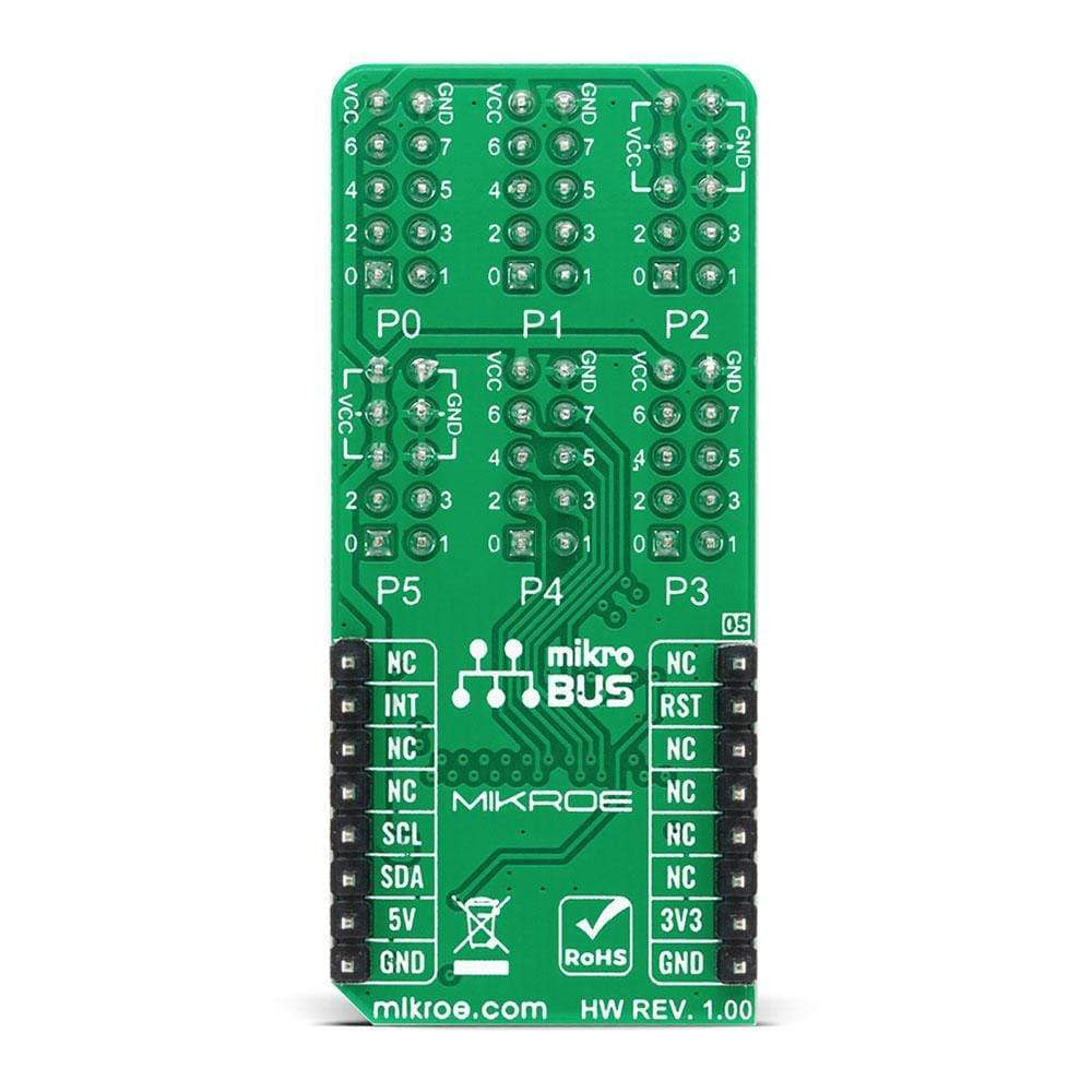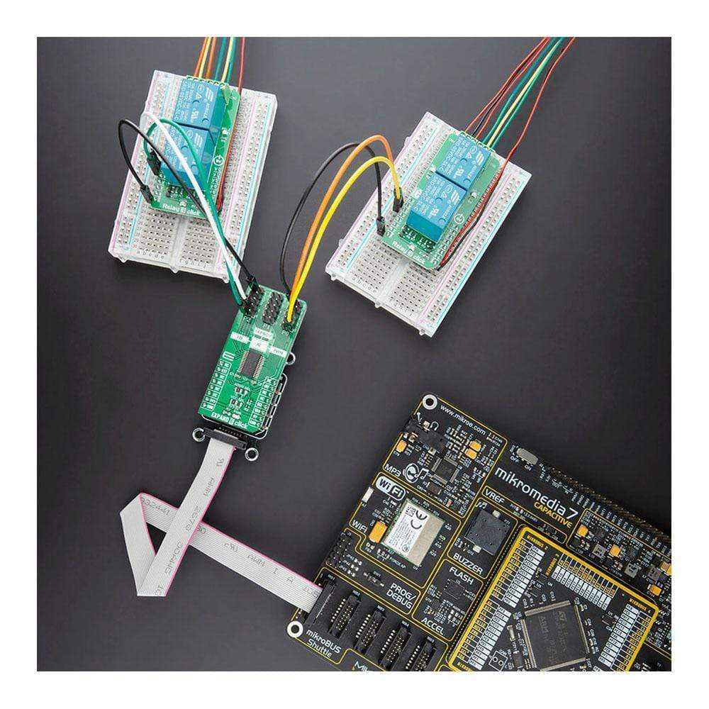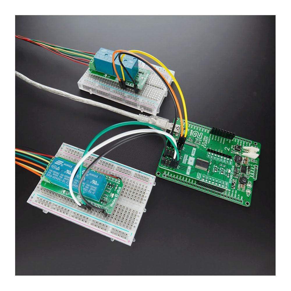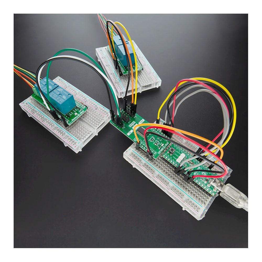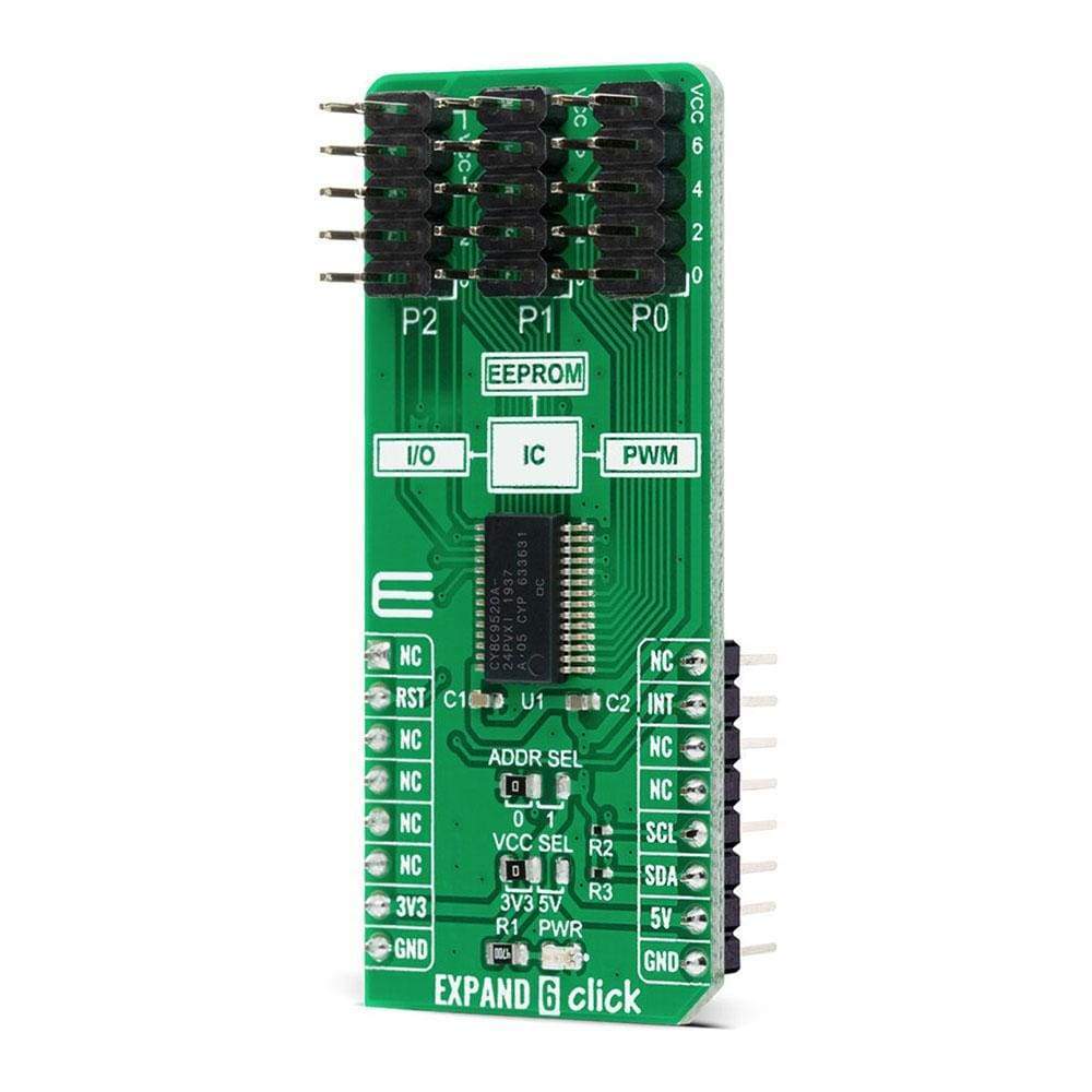
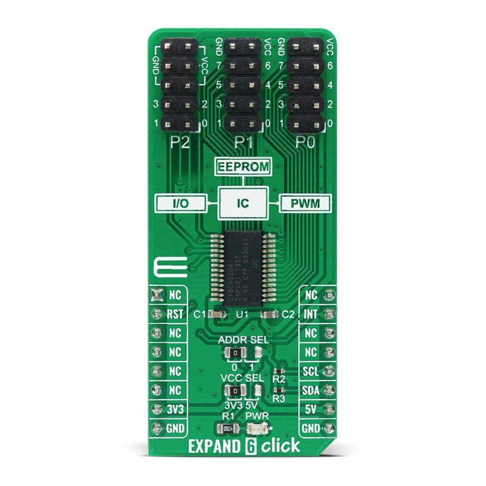
Expand 6 Click Board
Key Features
- 20-bit, 100kHz I2C port expander, flexible I2C address configuration, internal 3Kbyte EEPROM, user default storage, and more.
- The Expand 6 Click is based on the CY8C9520A, 20-bit I/O expander with EEPROM, and 4 independently configurable 8-bit PWM outputs from Cypress Semiconductor.
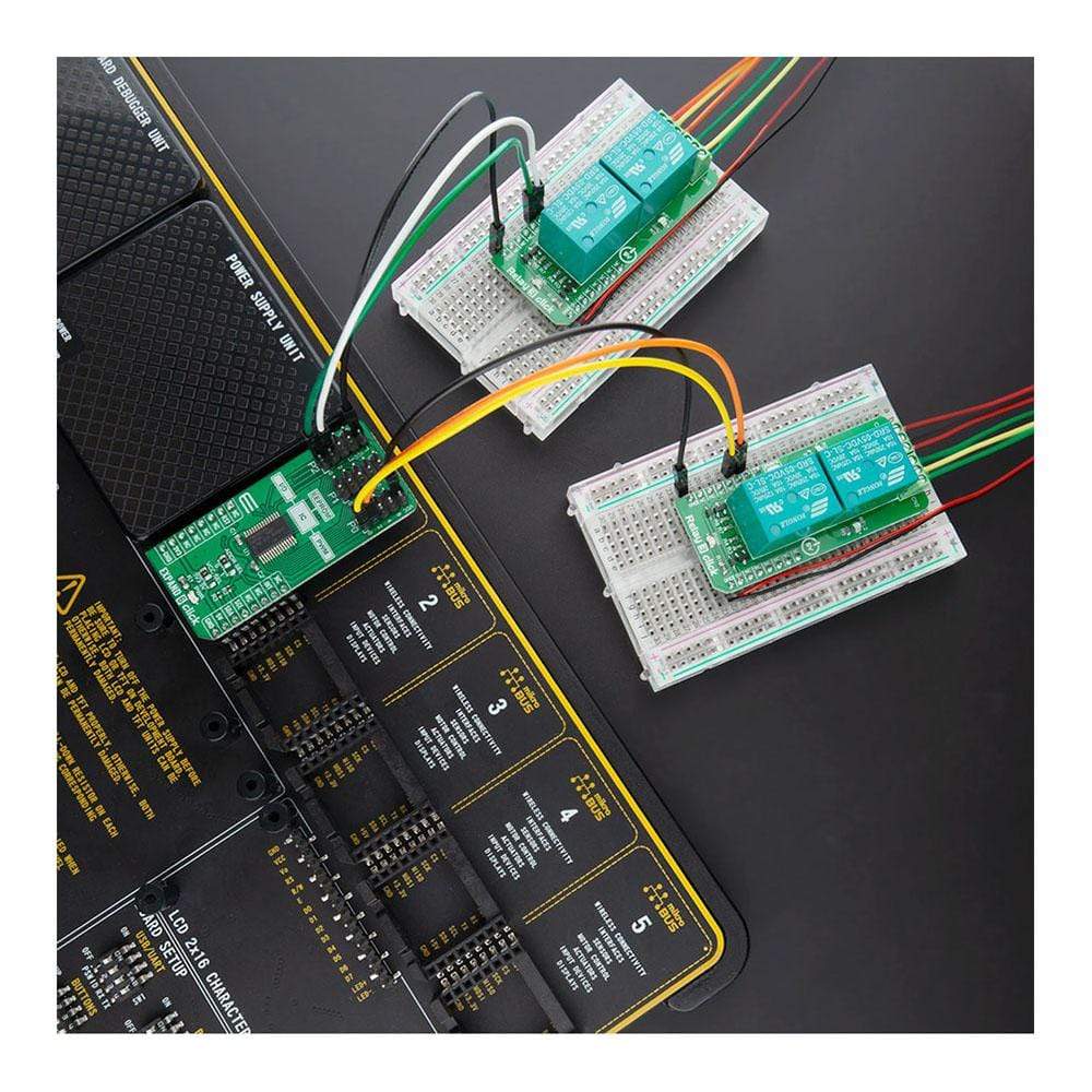
- Can be used to monitor and control LEDs and system intrusion detection devices, but also as a storage for information such as error codes or board manufacturing data for diagnostic purposes.
- mikroBUS: I2C Interface
Overview
The Expand 6 Click Board™ is a compact add-on board that contains an I2C configurable multi-port I/O expander with independently configurable pins as bi-directional input/outputs or PWM outputs. This board features the CY8C9520A, 20-bit I/O expander with EEPROM, and 4 independently configurable 8-bit PWM outputs from Cypress Semiconductor. The CY8C9520A operates as two I2C slave devices, first as a multi-port I/O expander, and second as a serial EEPROM with 3 Kbyte address space. It has a user default storage, flexible I2C address configuration, and a programmable interrupt function that indicates input pin level changes and PWM state changes. This Click Board™ can be used to monitor and control LEDs and system intrusion detection devices, but also as a storage for information such as error codes or board manufacturing data for diagnostic purposes.
The Expand 6 Click is supported by a mikroSDK compliant library, which includes functions that simplify software development. This Click Board™ comes as a fully tested product, ready to be used on a system equipped with the mikroBUS™ socket.
How Does The Expand 6 Click Board™ Work?
The Expand 6 Click Board™ is based on the CY8C9520A, 20-bit I/O expander with EEPROM, and 4 independently configurable 8-bit PWM outputs from Cypress Semiconductor. The main blocks of the CY8C9520A include the control unit, PWMs, EEPROM, and I/O ports. The I/O expander's data pins can be independently assigned as inputs, outputs, or PWM outputs, and can be configured as open-drain or collector, strong drive (10 mA source, 25 mA sink), resistively pulled up or down, or high impedance which can be selected in the Port Drive Mode register. It operates as two I2C slave devices, where the first device is a multi-port I/O expander (single I2C address to access all ports through registers), and the second device is a serial EEPROM with 3 Kbyte address space.
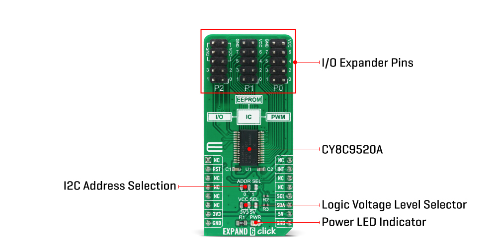
Configuration and output register settings are storable as user defaults in a dedicated section of the EEPROM. If user defaults were stored in EEPROM, they are restored to the ports at Power-Up. The EEPROM is byte readable and supports byte-by-byte writing. A pin 3 of the Port 2 on this Click board™ can be configured as an EEPROM Write Disable (WD) input that blocks write operations when set high. The configuration registers can also disable EEPROM operations.
EXPAND 6 Click communicates with MCU using the standard I2C 2-Wire interface with a maximum frequency of 100kHz. The CY8C9520A has, by default, two possible I2C slave address formats: the first is used to access the multi-port device, and the second to access the EEPROM. This selection of I2C slave addresses is performed by setting the logic level on the A0 pin of the CY8C9520A which can be done by using the SMD jumper labeled as ADDR SEL.
It also generates a programmable interrupt signal routed on the INT pin of the mikroBUS™, which can inform the system master that there is incoming data on its ports or that the PWM output state was changed. The reset signal routed on the RST pin of the mikroBUS™ socket is similar to POR (Power-ON Reset) function. When the CY8C9520A is held in Reset, all In and Out pins are held at their default High-Z State.
This Click board™ is designed to be operated with both 3.3V and 5V logic voltage levels that can be selected via VCC SEL jumper. This allows for both 3.3V and 5V capable MCUs to use the I2C communication lines properly.
SPECIFICATIONS
Type | Port expander |
Applications | Can be used to monitor and control LEDs and system intrusion detection devices, but also as a storage for information such as error codes or board manufacturing data for diagnostic purposes. |
On-board modules | EXPAND 6 Click is based on the CY8C9520A, 20-bit I/O expander with EEPROM, and 4 independently configurable 8-bit PWM outputs from Cypress Semiconductor. |
Key Features | 20-bit, 100kHz I2C port expander, flexible I2C address configuration, internal 3Kbyte EEPROM, user default storage, and more. |
Interface | I2C |
Compatibility | mikroBUS |
Click board size | L (57.15 x 25.4 mm) |
Input Voltage | 3.3V or 5V |
PINOUT DIAGRAM
This table shows how the pinout on EXPAND 6 Click corresponds to the pinout on the mikroBUS™ socket (the latter shown in the two middle columns).
Notes | Pin | Pin | Notes | ||||
---|---|---|---|---|---|---|---|
NC | 1 | AN | PWM | 16 | NC | ||
Reset | RST | 2 | RST | INT | 15 | INT | Interrupt |
NC | 3 | CS | RX | 14 | NC | ||
NC | 4 | SCK | TX | 13 | NC | ||
NC | 5 | MISO | SCL | 12 | SCL | I2C Clock | |
NC | 6 | MOSI | SDA | 11 | SDA | I2C Data | |
Power Supply | 3.3V | 7 | 3.3V | 5V | 10 | 5V | Power Supply |
Ground | GND | 8 | GND | GND | 9 | GND | Ground |
ONBOARD SETTINGS AND INDICATORS
Label | Name | Default | Description |
---|---|---|---|
LD1 | PWR | - | Power LED Indicator |
JP1 | VCC SEL | Left | Power Supply Voltage Selection 3V3/5V: Left position 3V3, Right position 5V |
JP2 | ADDR SEL | Left | Communication interface selection: Left position 0, Right position 1 |
J1-J3 | P0-P2 Port | - | I/O Expander Ports |
EXPAND 6 CLICK ELECTRICAL SPECIFICATIONS
Description | Min | Typ | Max | Unit |
---|---|---|---|---|
Supply Voltage | -0.5 | - | 6 | V |
High Level Source Current | 10 | - | - | mA |
Low Level Sink Current | 25 | - | - | mA |
Operating Temperature Range | -40 | +85 | °C |
Software Support
We provide a library for the Expand 6 Click Board™ on our LibStock page, as well as a demo application (example), developed using MikroElektronika compilers. The demo can run on all the main MikroElektronika development boards.
Library Description
The library covers necessary functions that enable the usage of the EXPAND 6 click board. You can check or set the state of every pin, set PWM output or use onboard user available EEPROM.
Key Functions
uint8_t expand6_read_pin ( uint16_t pin, uint8_t inv );
- Function is used to read the state of a defined pin.void expand6_write_pin ( uint16_t pin, uint8_t pin_val );
- Function is used to set a single output pin's logic level.void expand6_sel_pwm_pin ( uint16_t pin, uint8_t pwm_en );
- Function is used to enable or disable PWM output on a specific pin.
Example Description
The application is composed of three sections :
- System Initialization - Initializes I2C module, LOG structure and sets RST pin as output and INT pin as input.
- Application Initialization - Initalizes I2C driver and makes an initial log.
- Application Task - (code snippet) This example shows the capabilities of the EXPAND 6 click by toggling each of 20 available pins.
void application_task ( ) { mikrobus_logWrite( " PORT 0 ", _LOG_LINE ); for ( pin_num = 0; pin_num < 8; pin_num++ ) { expand6_write_port( EXPAND6_PORT_0, 0xFF ); expand6_write_pin( pin_num, EXPAND6_LOW ); mikrobus_logWrite( "Pin ", _LOG_TEXT ); ByteToStr( pin_num, log_txt ); Ltrim( log_txt ); mikrobus_logWrite( log_txt, _LOG_TEXT ); mikrobus_logWrite( " is low!", _LOG_LINE ); Delay_ms( 500 ); expand6_write_port( EXPAND6_PORT_0, 0xFF ); } Delay_ms( 1000 ); mikrobus_logWrite( " PORT 1 ", _LOG_LINE ); for ( pin_num = 8; pin_num < 16; pin_num++ ) { expand6_write_port( EXPAND6_PORT_1, 0xFF ); expand6_write_pin( pin_num, EXPAND6_LOW ); mikrobus_logWrite( "Pin ", _LOG_TEXT ); ByteToStr( pin_num, log_txt ); Ltrim( log_txt ); mikrobus_logWrite( log_txt, _LOG_TEXT ); mikrobus_logWrite( " is low!", _LOG_LINE ); Delay_ms( 500 ); expand6_write_port( EXPAND6_PORT_1, 0xFF ); } Delay_ms( 1000 ); mikrobus_logWrite( " PORT 2 ", _LOG_LINE ); for ( pin_num = 16; pin_num < 20; pin_num++ ) { expand6_write_port( EXPAND6_PORT_2, 0xFF ); expand6_write_pin( pin_num, EXPAND6_LOW ); mikrobus_logWrite( "Pin ", _LOG_TEXT ); ByteToStr( pin_num, log_txt ); Ltrim( log_txt ); mikrobus_logWrite( log_txt, _LOG_TEXT ); mikrobus_logWrite( " is low!", _LOG_LINE ); Delay_ms( 500 ); expand6_write_port( EXPAND6_PORT_2, 0xFF ); } mikrobus_logWrite( "-------------------", _LOG_LINE ); Delay_ms( 1000 ); }
The full application code, and ready to use projects can be found on our LibStock page.
Other mikroE Libraries used in the example:
- I2C
- UART
- Conversions
Additional Notes and Information
Depending on the development board you are using, you may need a USB UART click, USB UART 2 click or RS232 click to connect to your PC, for development systems with no UART to USB interface available on the board. The terminal available in all MikroElektronika compilers, or any other terminal application of your choice, can be used to read the message.
mikroSDK
This Click board™ is supported with mikroSDK - MikroElektronika Software Development Kit. To ensure proper operation of mikroSDK compliant Click board™ demo applications, mikroSDK should be downloaded from the LibStock and installed for the compiler you are using.
Frequently Asked Questions
Have a Question?
Be the first to ask a question about this.