


Mikroelektronika d.o.o.
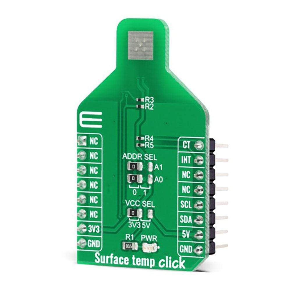
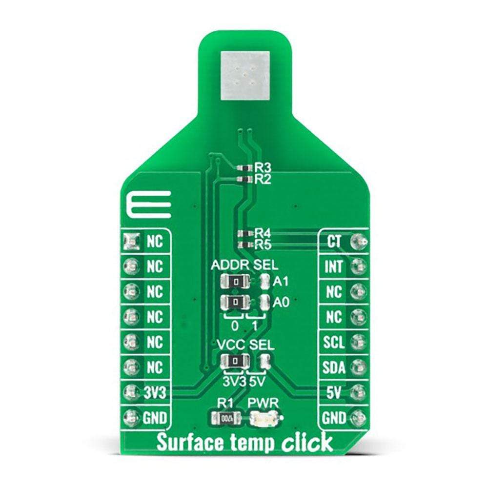
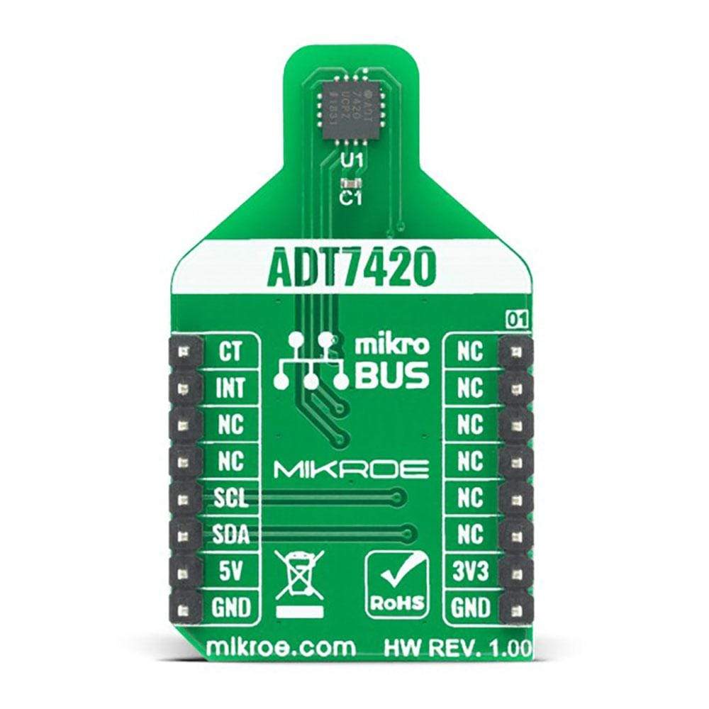
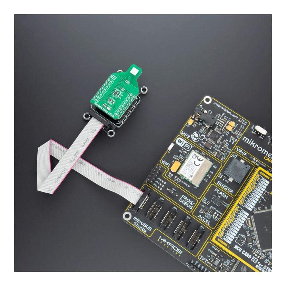
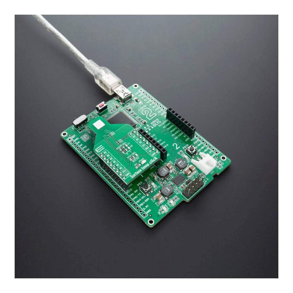
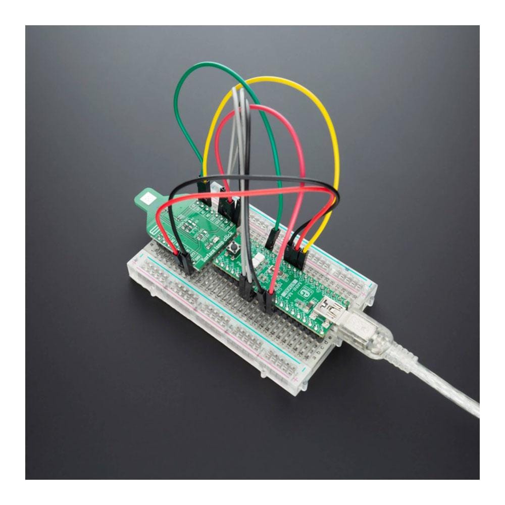
Surface Temp Click Board™
Surface Temp Click Board™
SKU: MIKROE-4205
Couldn't load pickup availability
Overview
The Surface Temp Click Board™ is high accuracy digital temperature sensor Click Board™, offering breakthrough performance over a wide industrial range. It is equipped with the ADT7420 - an accurate 16-Bit Digital I2C temperature sensor from Analog Devices. It features high-temperature accuracy, ultralow temperature drift (0.0073°C), fast first temperature conversion on power-up, no temperature calibration/correction required, and more useful features which makes this Click Board™ a great choice for RTD and thermistor replacement, medical equipment, food transportation and storage, environmental monitoring, HVAC, and many more.
Downloads
How Does The Surface Temp Click Board™ Work?
The Surface Temp Click Board™ is based around the ADT7420 which has a 16-bit ADC to monitor and digitize the temperature to 0.0078°C resolution. The ADC resolution, by default, is set to 13 bits (0.0625°C) and is a user programmable mode that can be changed through the serial interface.
The ADT7420 is guaranteed to operate over supply voltages from 2.7 V to 5.5 V. Operating at 3.3 V, the average supply current is typically 210 μA. The ADT7420 has a shutdown mode that powers down the device and offers a shutdown current of typically 2.0 μA at 3.3 V. The ADT7420 is rated for operation over the −40°C to +150°C temperature range.
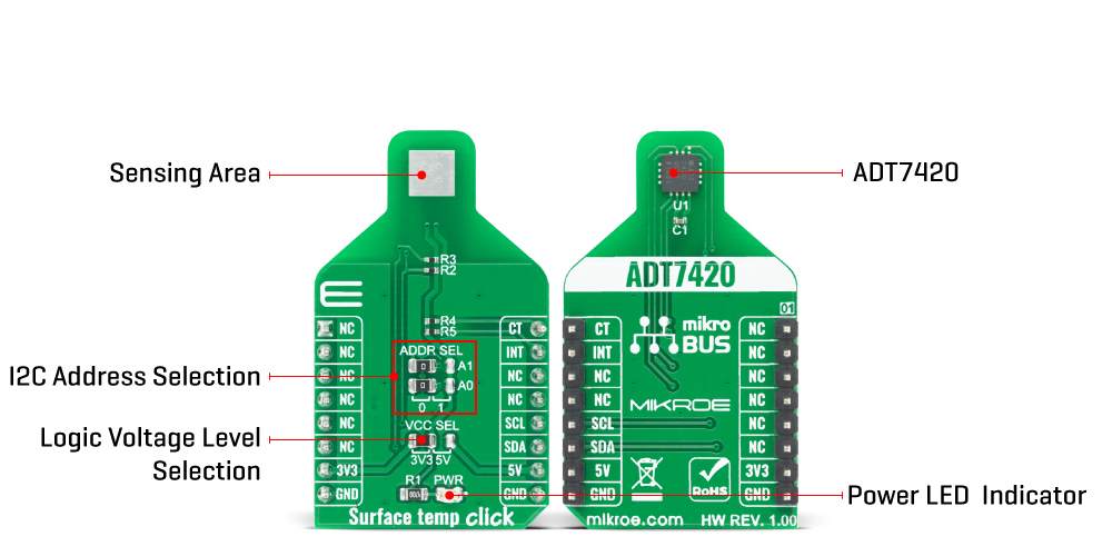
The Surface Temp Click Board™ have a sensing pad, which is thermally connected to a ADT7420, for temperature sensing. The internal temperature sensor has high accuracy and linearity over the entire rated temperature range without needing correction or calibration by the user.
In normal mode (default power-up mode) the ADT7420 runs an automatic conversion sequence. During this automatic conversion sequence, a conversion typically takes 240 ms to complete and the ADT7420 is continuously converting. This means that as soon as one temperature conversion is completed, another temperature conversion begins. Each temperature conversion result is stored in the temperature value registers and is available through the I2C interface. In continuous conversion mode, the read operation provides the most recent converted result.
Like most I2C-compatible devices, the ADT7420 has a 7-bit serial address. The address can be selected by JP2 and JP3 jumpers (details in ADT7420 datasheet). Pin A0 and Pin A1 are available for address selection, giving the ADT7420 four possible I2C addresses.
The INT and CT pins have two under-temperature/over-temperature modes: comparator mode and interrupt mode. The interrupt mode is the default power-up overtemperature mode. The CT pin is an open-drain output that becomes active when the temperature exceeds a programmable critical temperature limit. The INT pin is also an open-drain output that becomes active when the temperature exceeds a programmable limit. The INT pin and CT pin can operate in comparator and interrupt event modes.
The voltage range which can be used to power up the Surface Temp Click Board™, allows it to work with controllers which have GPIO on both 3.3V and 5V. It can be selected by soldering a small SMD jumper, labelled as VCC SEL to the correct position. As well as PWR LED indicator for signaling that power is present on the system.
SPECIFICATIONS
| Type | Temperature |
| Applications | RTD and thermistor replacement, Thermocouple cold junction compensation, Medical equipment, Industrial control and test, Food transportation and storage, Environmental monitoring and HVAC, Laser diode temperature control. Programmable interrupts. Low power. |
| On-board modules | ADT7420 |
| Key Features | High accuracy digital temperature sensor offering breakthrough performance over a wide industrial range. 16-bit ADC to monitor and digitize the temperature to 0.0078°C resolution. |
| Interface | I2C |
| Compatibility | mikroBUS |
| Click board size | M (42.9 x 25.4 mm) |
| Input Voltage | 3.3V or 5V |
PINOUT DIAGRAM
| Notes | Pin | Pin | Notes | ||||
|---|---|---|---|---|---|---|---|
| NC | 1 | AN | PWM | 16 | CT | Critical Overtemp Indicator | |
| NC | 2 | RST | INT | 15 | INT | Overtemp and Undertemp Indicator | |
| NC | 3 | CS | RX | 14 | NC | ||
| NC | 4 | SCK | TX | 13 | NC | ||
| NC | 5 | MISO | SCL | 12 | SCL | I2C Clock | |
| NC | 6 | MOSI | SDA | 11 | SDA | I2C Data | |
| Power Supply | 3.3V | 7 | 3.3V | 5V | 10 | 5V | Power Supply |
| Ground | GND | 8 | GND | GND | 9 | GND | Ground |
ONBOARD SETTINGS AND INDICATORS
| Label | Name | Default | Description |
|---|---|---|---|
| LD1 | PWR | - | Power LED Indicator |
| JP1 | VCC SEL | Left | Power supply voltage selection: left position 3V3, right position 5V |
| JP2 | PWR | Left | Slave address selection: Left position 0, right position 1 |
| J3 | PWR | Left | Slave address selection: Left position 0, right position 1 |
SURFACE TEMP CLICK ELECTRICAL SPECIFICATIONS
| Description | Min | Typ | Max | Unit |
|---|---|---|---|---|
| Supply Voltage | 2.7 | - | 5.5 | V |
| Temperature accuracy from −20°C to +105°C | - | ±0.25 | - | °C |
| Temperature drift | - | 0.0073 | - | °C |
| Power consumption at 3.3 V in normal mode | - | 700 | - | µW |
| Power consumption at 3.3 V in shutdown mode | - | 7 | - | µW |
| Resolution | - | 16 | - | bit |
| General Information | |
|---|---|
Part Number (SKU) |
MIKROE-4205
|
Manufacturer |
|
| Physical and Mechanical | |
Weight |
0.025 kg
|
| Other | |
EAN |
8606027380044
|
Frequently Asked Questions
Have a Question?
Be the first to ask a question about this.